ZePrA | Configurations | PDF


Define Settings for PDF Processing
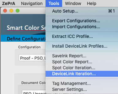
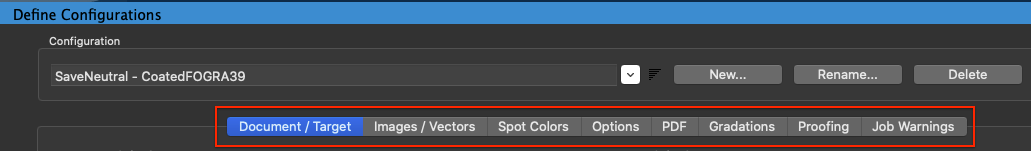
In the Configurations/PDF tab, Transparency/Overprinting, PDF/X-specific information, Advanced Options and PDF Layer rules can be defined.
PDF/X-specific information is recommended when ZePrA is used to create the print data. The print shop receiving the PDF/X data can determine from the PDF/X entries for which print standard the PDF/X files have been optimized.
ZePrA supports the following PDF/X standards:
- PDF/X-1a
- PDF/X-3
- PDF/X-4
- PDF/X-5n
PDF/X
PDF/X-specific information is recommended when ZePrA is used to create the print data. The print shop receiving the PDF/X data can determine from the PDF/X entries for which print standard the PDF/X files have been optimized.
PDF/X Output Intent: The output intent is a color profile containing the printing color space for which the PDF file was created.
Four presets are available in the drop-down menu:
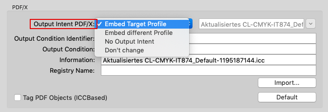
Selection of the PDF/X Output Intent
Embed Target Profile: The default setting. The target profile is embedded as output intent
Embed different Profile: A manually selected profile is embedded as output intent
No Output Intent: Removes the output intent
Don’t change: Output intent remains as is.
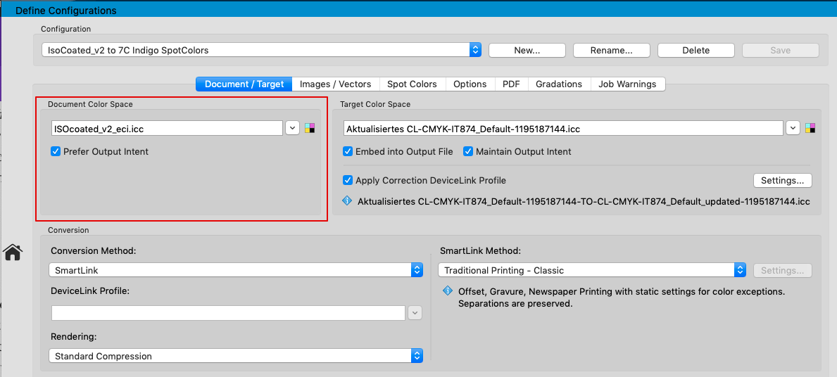
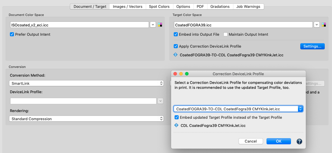
Note: If a Correction DeviceLink Profile has been selected in the Document/Target tab under Target Color Space and the checkbox Embed updated Target Profile instead of the Target Profile has been activated under Settings, then this corrected target profile is embedded as output intent.
Output Condition Identifier: Indicates the color measurement data on which the color profile of the output intent is based. This information is important because there are profiles with sometimes quite different names for print standards from different providers. If a print shop receives PDF/X data from users who work with different profiles, it can use Output Condition Identifier to determine whether it is a profile for an industry standard or a custom profile.
Output Condition Identifier: Enter the description of the printing standard for which the PDF/X data was optimized.
Information: Customer, job, printing process or file specific entries can be entered here.
Registry Name: At www.color.org the ICC maintains a registry for colorimetric data and output conditions representing international printing standards. If a print shop works with many different suppliers, it is advisable to agree on a name/output condition identifier registered with the ICC.
Import: When a PDF/X file is loaded using Import, ZePrA extracts the PDF/X information it contains. It is then no longer necessary to enter the information manually.
Note: When using ColorLogics DeviceLink Sets with the extensions CoLoV3/V4/V5/V6, they contain information that is automatically entered in the corresponding fields for PDF/X information in ZePrA. When creating Queues with Auto Setup, no manual entries in the PDF/X information are necessary when using ColorLogic DeviceLinks. Similarly, no manual entries are necessary when working with a target profile that ZePrA recognizes as a standard output profile.
Note: For custom DeviceLink profiles, CoPrA's Profile Manager tool allows to make the entries required for automatic transfer of PDF/X information to ZePrA very easily in the Workflow tab.
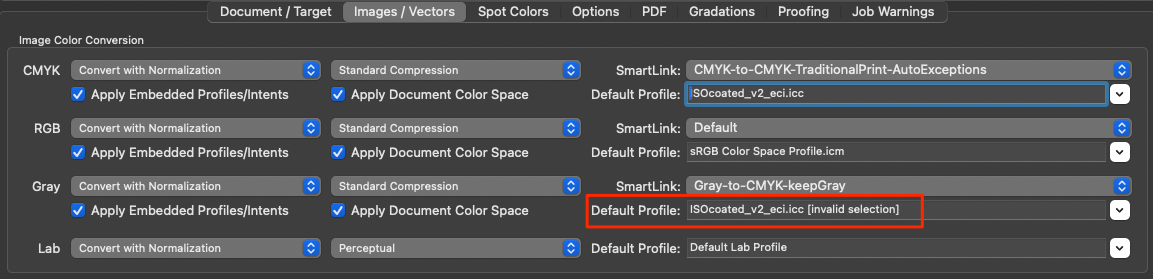
Tag PDF Objects (ICCBased): Assigns the target profile to each object in the PDF file after color conversion. Can be used if a PDF file is not a PDF/X file, but you want to ensure that the color information for images and vectors is correctly defined with the target profile. By default, this option is disabled and we recommend using it only when necessary.
Advanced Options
PDF Passwords: Passwords in PDF files prevent data from being converted. Enter the password to remove the password protection and to enable conversions.
Pages: Specifies which pages are converted for PDF files with multiple pages. Pages can be selected individually if they require different color conversions.
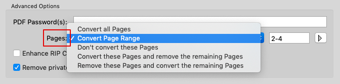
Selection of pages to convert
Convert all Pages: The default setting. Converts all pages of the PDF document
Convert Page Range: Converts specific pages of a multi-page PDF document. Enter the relevant page numbers or range. Multiple page numbers are separated by commas (for example 3,5,8), page ranges are hyphenated (for example 5-9).
Don’t convert these Pages: Converts all but selected pages.
Convert these Pages and remove the remaining Pages: Extracts and converts the specified pages. The remaining pages are removed.
Remove these Pages and convert the remaining Pages: Removes the specified pages. Converts the remaining pages.
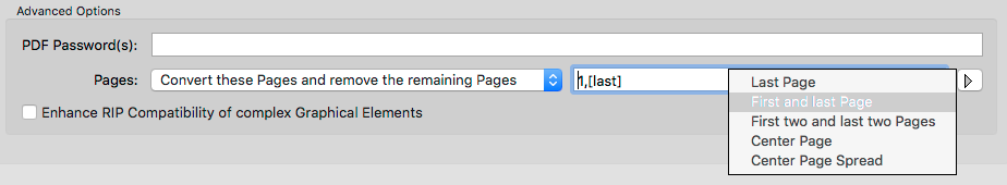
Additional page selection rules can be selected by clicking the arrow button
Enhance RIP Compatibility of complex Graphical Elements: ZePrA converts all objects, including vector shading, with high accuracy and 16-bit precision. For every shading created based on a function in the original file, it is necessary to use a very large LUT (look up table) to ensure a correct color transformation.
Some RIPs (e.g. EFI Fiery and Global Graphic Multi RIP) have issues in handling 16-bit shading and large LUT’s. To avoid issues and to speed up processing time of certain RIPs, the option Enhance RIP Compatibility of complex Graphical Elements can be used. This option is disabled by default in all existing configurations and for all new configurations created using the Auto Setup Wizard. Activate this option whenever processing issues with a RIP occur after converting files with ZePrA.
Remove private Data of other Applications: Removes private application data from PDF files. Such data can be stored optionally by Adobe Photoshop or Illustrator when saving files as PDF.
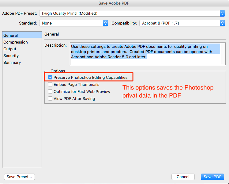
However, other programs can use so-called “piece information” in PDFs as well to place non-public application data in PDF files. This allows the subsequent opening and editing of the original file in the previously mentioned applications. However, for color converted files this application data can be misleading as it will not be converted. Reopening these files in the above mentioned applications will then only display the original but not the converted color information. Additionally, PDF files which contain piece information can be significantly larger. To obtain smaller files (without piece information after conversion of PDF files) select the function Remove private Data of other Applications.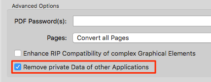
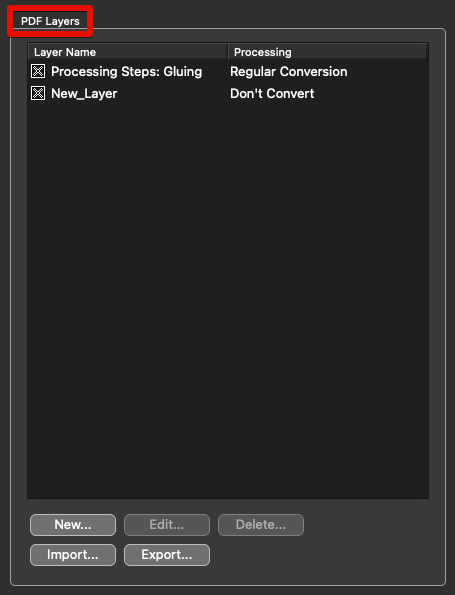
PDF Layers
ZePrA 7 and higher supports ISO 19593-1:2018 (Processing steps for packaging and labels). It is common practice in the packaging segment and other segments of the printing industry to work with PDF files that contain graphic objects to be printed and additional graphic objects and metadata for use in other steps in the production of the final product. These non-printing PDF objects and metadata are important for processing steps like die cutting or creasing.
Definition of processing step: Step in production of print products other than regular printing of color on the print surface. Example: Cutting, printing of white, varnish or similar. A layer is recognized as a processing step by its metadata in the layer dictionary of the PDF ("optional content group"). The feature also works for layers which are not covered by the "Processing Steps" standard. In this case, the layer name is specified by the user.
The PDF Layers feature allows you to define rules which specify how individual layers are processed. When applied to PDF files, only the content of selected layers can be converted, while the content of unselected layers remains untouched or can be deleted.
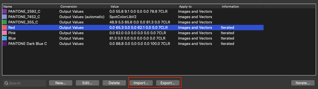
Export and Import: These functions allow you to export rules from a configuration and import them into another configuration.
Procedure
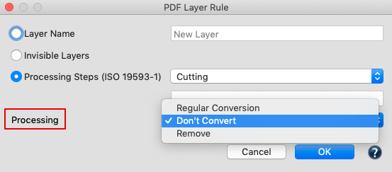
Double-clicking a rule or hitting New opens the PDF Layer Rule dialog. Each rule specifies the processing of the selected layer(s). The following options are available:
Layer Name: Enter the name of the layer to be associated with a Processing option. Layer names may contain wildcards, e.g. * means all layer names.
Invisible Layers: Selects all layers which are switched off and are therefore invisible in PDF viewers such as Acrobat.
Processing Steps: Defines layers which are marked as Processing Step according to ISO 19593-1. The processing step type can be chosen from the menu. All means all processing steps. Custom means a processing step name as specified in the text field.
Processing defines how a selected layer is to be treated:
- Regular Conversion:The layer is converted as usual.
- Don't Convert: Excludes layer from the color conversion.
- Remove: The layer is removed from the converted PDF file.
General considerations
- In PDF files, graphical elements can be associated with any number of layers. For each element, ZePrA searches the list of layer rules from top to bottom for a rule that matches the layer name of that element. The first matching rule found will then be applied. Subsequent rules will be ignored, which means, that only one rule is applied to each graphical element.
- If an element is associated with more than one layer and there are several matching rules for these layers with different processing options, for example, if the first layer is set to Don't Convert and the next is set to Remove, the result depends on the order in which the rules appear in the list.
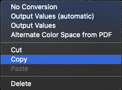
- Make sure to list layer rules in an appropriate order in ZePrA. Open the context menu and use Cut to cut a layer, select a different position of the mouse and Paste to change the order of rules at any time.
- Layers set to Remove will be removed from the OCProperties list and will not appear in the layer panel of Adobe Acrobat.
- Spot color conversion for spot colors which were removed with layers do not appear in the job report.
- When a file is flattened, it's layer structure is destroyed. Therefore, to preserve a layer, ZePrA extracts it from the PDF before flattening and merges it thereafter.
- A potential special error can occur when layer rules preserve layers that are merged at the end of the painting order. This means if in the original file a part of a preserved layer is covered by another element which is painted later, this layer is no longer covered in the converted file. Currently, there is no solution for this problem, on the other hand it might be of no importance in practice.
- ZePrA can rasterize a file to PDF while retaining the layers. The result is a single image containing the rasterized document with the layers on top.