ZePrA | Share with ZePrA

Share with ZePrA

Use CoPrA’s DeviceLink settings in ZePrA

Share CoPrA’s DeviceLink settings with ZePrA

Sharing settings with ZePrA (CoPrA 5 and lower)

Due to the close connection between CoPrA (ColorLogic’s profiling solution) and our color server ZePrA, the profile settings from CoPrA can be used to calculate DeviceLink profiles in ZePrA.

By selecting the checkbox Share with ZePrA in CoPrA, the settings of your DeviceLink and SaveInk profiles are transferred directly to ZePrA and can be used there as SmartLink Method.

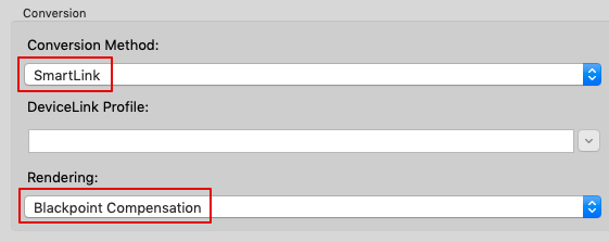
The SmartLink Method in ZePrA allows calculation of the necessary DeviceLink and/or SaveInk profiles for the conversion of PDF files on-the-fly, without the need to create these DeviceLinks in advance.

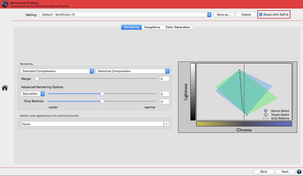
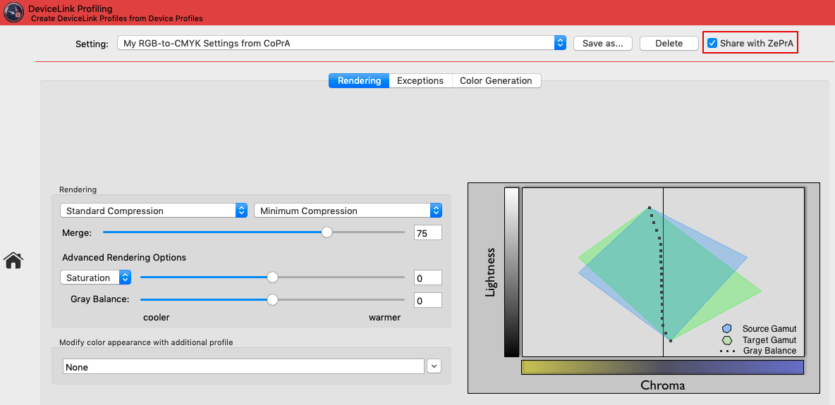
The DeviceLink tool in CoPrA: SmartLink can use the profile settings from CoPrA to create DeviceLinks in ZePrA

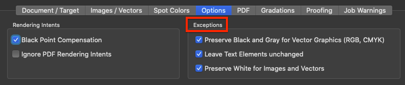
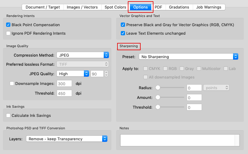
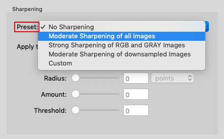
To do so, make all the required settings in CoPrA by entering all relevant information in the DeviceLink tool under Rendering, Exceptions, and Color GenerationClick Save As and enter a name for the setting. Confirm with OK, then activate the Share with ZePrA checkbox. 

The so created methods shared with ZePrA are then available as SmartLink Method in the drop-down menus of both the Auto Setup and the Configurations.

Note: Only saved settings can be shared with ZePrA. Default or edited presets cannot be shared.

Sharing settings with ZePrA (CoPrA 6 and higher)

The SmartLink Method in ZePrA allows to create DeviceLinks and SaveInk profiles for the conversion of PDF files on-the-fly, without the need to create these DeviceLinks in advance.
Due to the close linkage between CoPrA and ZePrA, profiling settings specified in CoPrA can be used by ZePrA to create the required profiles.

The settings are accessible via a shared folder which has the advantage that CoPrA and ZePrA do not need to be installed on the same computer. The shared folder must simply be accessible by both ZePrA and CoPrA, either over the network, a shared local folder or the cloud.

Procedure

In CoPrA

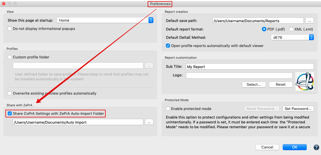
  1. Under Preferences, enable the checkbox Share CoPrA Settings with ZePrA Auto Import Folder and select ZePrA’s Auto Import folder.
    Note: The Auto Import folder must be activated in ZePrA as well.
    If the checkbox is enabled and the Preferences dialog closed with OK an information message will appear asking the user if all shared presets should now be copied to the defined Auto-Import Folder.

  2. In the DeviceLink tool, define all required settings by entering all relevant information under Rendering, Exceptions and Color Generation.
  3. Click Save As and enter a name for the setting. Confirm with OK, then activate the Share with ZePrA checkbox.

  4. CoPrA Settings created that way and shared with ZePrA are available for selection as SmartLink Method in the drop-down menus of both the Auto Setup and the Configurations settings.

Note: Only saved settings can be shared with ZePrA. Default or edited presets cannot be shared.

In ZePrA

Make sure to enable the Auto Import function in ZePrA’s Preferences and to use the same folder as CoPrA. CoPrA’s DeviceLink and SaveInk settings are now accessible in ZePrA and can be used there as a SmartLink Method. SmartLink can now create custom DeviceLinks which can be used in ZePrA configurations.

Basic information on the Auto Import folder

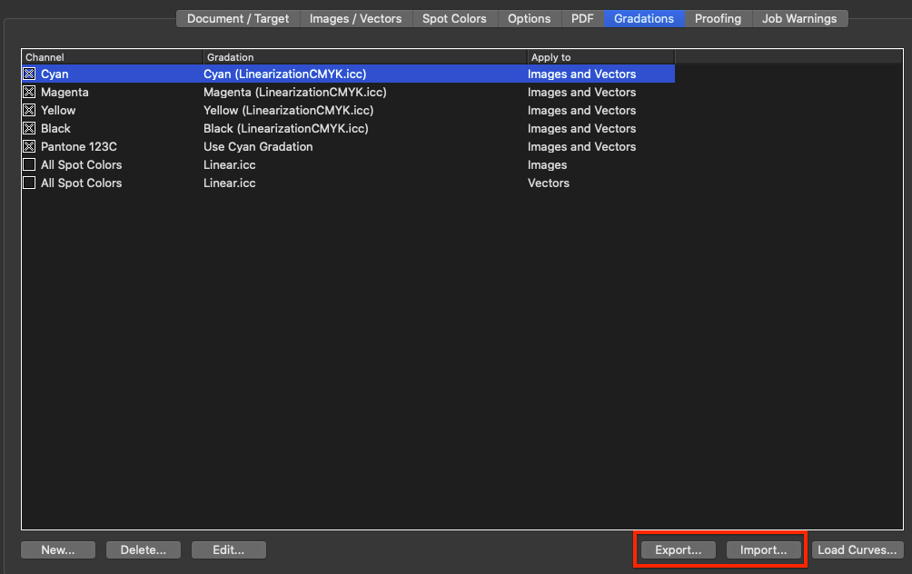
Files (such as ICC profiles, configurations, spot color libraries, gradations or SmartLink settings) that are moved or copied into the Auto Import folder are transferred to ZePrA’s internal dataset and can then be used by ZePrA.
When the file in the Auto Import folder is replaced by a newer version, it will be updated in ZePrA’s internal datasets as well.
Note: If a file in the Auto Import folder is deleted, it is not deleted in ZePrA’s internal dataset. For example if a SmartLink setting has been deleted in the Auto Import folder, it is still available in ZePrA’s internal dataset and if this setting is deleted in ZePrA’s dataset, it is still available in the Auto Import folder.

ZePrA | Configurations | Gradations

Gradations

Customize Gradation settings for specific configurations

Adding Gradations to a Configuration

Overview

Gradations are curves that can be applied to the individual data channels after color conversion. The procedure is similar to that for controlling the curves when imaging printing plates. Tone value corrections can be applied to both CMYK channels and to spot color channels with the help of gradations.

To apply gradation curves to otherwise print ready data with ZePrA, create corresponding configurations using the Auto Setup Wizard. The document color space will not be changed.

It is best to apply pure gradation corrections to print ready PDF/X 1a files that are comprised of only CMYK and possibly spot colors. For more detailed information Gradations and Auto Setup Wizard – Apply gradation curves only.

Applying Gradations

Via the Configurations option on the Sidebar, access the Define Configuration window and the Gradations tab. Not only can gradation adjustments be applied in the form of predefined gradation curves, but also gradation adjustments can be loaded from an external file and automatically applied to process and spot colors. This is also possible without any prior color management on process and/or spot colors. When updating the curves in this external file, the gradation curves are automatically adopted in the ZePrA configuration and applied to the printing data being processed. This enables short term adjustments of the pronging data without having to change the CTP curves in the RIP. With ZePrA, automatic color and printing control is possible not only for standard printing processes but also for digital printing machines. The gradation curves can be applied to both CMYK and the spot color changes of the file to be converted.

The basic colors Cyan, Magenta, Yellow, Black, as well as the entry All Spot Colors appear as fixed values at the top of the list and cannot be deleted or renamed. All Spot Colors allows to adjust all spot colors of the document quickly in one go. All DeviceN spot colors will be adjusted using the same (assigned) gradation curve.

The basic colors Cyan, Magenta, Yellow, Black, as well as the entries All Spot Colors (Images) and All Spot Colors (Vectors) appear as fixed values at the top of the list and cannot be deleted or renamed. All Spot Colors allows you to adjust all spot colors of the document quickly in one go. Since there are two entries for All Spot Colors (images and vectors) both entries must be changed if the same curve is to be applied to images and vectors. All DeviceN spot colors will be adjusted using the same (assigned) gradation curve.

Notes

  • When old configurations are loaded or imported and Apply Gradations to Images/Vector Graphics is disabled, the gradation rules will be modified accordingly.
  • Configurations which use individual image and vector rules should not be used in older ZePrA versions.

A right click on a channel opens a context menu which allows you to Cut, Copy, Paste or Delete the selected entry.

New: Creates further entries for adjusting the gradation of spot colors. Enter the Channel Name and select the required gradation curve.

Delete: Deletes the selected channel.

Edit: Opens the Edit Gradation Rule window to edit existing channels.

Channel Name: Enter a new name for the selected channel.

Gradation: Select a gradation curve.

Apply to: Applies the selected gradation curve to Images, Vectors or Images and Vectors.
Note: Individual curves can be applied to Images and Vectors by setting up two rules for one channel (for example, the Cyan channel), with one curve assigned to images and the other curve assigned to vectors.

Export and Import: This allows you to export gradation rules from one configuration and import them into another configuration.

Load Curves: Loads an external file that includes the gradation corrections for the process color(s) to be changed. There are two options to load gradation curves:

  1. Select Curves
    Select linearization DeviceLink profiles created by CoPrA or previously imported files including curves (gradations).
    Gradation curves created with CoPrA’s Linearization tool are saved in the Profiles folder and are automatically listed in ZePrA’s Select Curves drop-down menu. Only curves with a matching color space are shown. These curves are read only and cannot be edited in ZePrA’s Gradation tool. When changing the gradation curves (e.g. by overwriting the .icc file in CoPrA with differing linearization data), these changes will automatically be applied to all configurations using these curves. The location of the selected .icc file is not important (e.g. Profile or Auto Import folder).
  2. Use Curves from File
    Loads external files including the gradation corrections for the curves (gradations) to be changed.
    The curves created with ZePrA or duplicated from imported text files are saved as single-channel ICC DeviceLink profiles in the operating system’s profile folder. In addition to the curves included in ZePrA for tonal corrections from -20% to +20%, the drop-down menu also shows all gray-to-gray DeviceLink profiles located in the operating system’s profile folder. Note that only the curves created in ZePrA can be edited in ZePrA. Write-protected gradation curves can be duplicated and the duplicates can be edited.
    Imported text files are stored internally and temporarily, but not as DeviceLink profiles. These curves are therefore not editable in ZePrA.

Note: Gradation curves created with ZePrA’s Gradations tool are saved in the system folder for ICC profiles and are automatically listed in the Gradation drop-down menus under New/Edit. The curves can also be accessed via Load Curves/Use Curves from File. If you change the gradation curves using ZePrA’s Gradations tool, these changes are automatically applied to all configurations that use these curves.

Importing CTP Compensation Curves

Utilizing ZePrA to automate a workflow using external gradation files and import existing CTP compensation curves or correction gradations into ZePrA, a separate tool will be necessary that calculate the respective correction curves based on measurements on printed sheets and saves them into the following form as text or XML files:

BEGIN_DATA_FORMAT

GRAY    CMYK_C    CMYK_M    CMYK_Y    CMYK_K

END_DATA_FORMAT

BEGIN_DATA

0.00     0.00     0.00     0.00     0.00

1.00     0.69     0.58     0.53     0.65

3.00     2.02     1.76     1.62     1.92

5.00     3.23    2.60     2.38     3.28

10.00     6.95    5.92     5.52     7.41

15.00     10.80     9.64     9.02     11.93

20.00     15.10     13.29     12.43     16.68

25.00     19.53     17.19     16.06     21.52

30.00     24.07     21.88     20.37     26.37

35.00     29.08     26.91     24.94     31.26

40.00     34.12     31.50     28.69     36.24

45.00     39.33     36.43     32.94     41.68

50.00     43.80     41.84     37.96     46.59

55.00     49.20     47.98     43.81     51.42

60.00     55.37     54.01     50.29     57.48

65.00     61.91     60.59     57.36     63.44

70.00     68.46     66.28     63.78     69.11

75.00     74.90     72.54     70.73     74.58

80.00     79.24     78.89     77.66     79.52

85.00     85.08     83.09     82.28     84.93

90.00     89.42     87.13     86.64     89.33

95.00     93.74     92.60    92.40     94.02

97.00     95.66     95.25     95.13     96.03

99.00     98.18    98.01     97.98    98.31

100.00      100.00     100.00     100.00     100.00

In this example, Gray stands for the input values in percent (0-100%) and CMYK_C stands for the output values of the Cyan channel in percent (0- 100%). The example shows a step wedge with 25 gradations of the process colors in CMYK. The number of levels is arbitrary and depends on the measuring wedge.

Note: The curves created using ZePrA or curves duplicated from imported text files are stored as one-channel ICC DeviceLink profiles in the profiles folder of the operating system. The drop down menu shows not only the curves supplied with ZePrA for tone value corrections from -20% to +20%, but all Gray-to-Gray DeviceLink profiles contained in the profiles folder of the operating system. Please note that only the curves created in ZePrA can be edited in ZePrA. Imported text files are stored internally and temporarily, but not as DeviceLink profiles. A separate license is necessary in order to be able to use the Gradation functions. Read-only gradation curves can be duplicated in curve management and these duplicates can be edited.

Automatic Gradation Correction of an Existing Configuration

To furnish existing configurations with the required gradation adjustments using an external file and automate workflows:

  1. Open the Gradations tab in the Define Configurations window
  2. Click the Import button
  3. Select the external file with the required gradation adjustments

In some situations, the format will need to be changed in the Import dialog from configuration file (*.ccf) to text file (*.txt) to be able to import the gradation file. ZePrA assigns the gradation curves found in the file automatically to the right process colors. If spot color curves are also stored in the external gradation file, ZePrA creates the corresponding spot color channel names in the configuration and assigns the appropriate curve to each color. The curve loaded for the selected channel is displayed in a small overview chart.

The configuration is now linked with the external gradation file. If the file is updated because of new measurements on the printed sheet and needs to be overwritten with new gradation curves, ZePrA recognizes the changes and automatically adopts the updated curves.

Gradation curves that originated from loaded text files can be deleted using the Create Gradations dialog. When deleting gradations that are still being used in Configurations, a warning will appear. If this warning is ignored, the gradations in the respective configuration will be deleted and replaced with a linear gradation. Ultimately, when deleting one curve not only the single curve but all curves linked with the file will be deleted.

Applying Gradation Curves to Spot Color Channels

To be able to apply gradation curves to spot color channels, select New and enter the exact name of the spot color. The name of the spot color channel must match the name used for the spot color in the file.

Example:  If the spot color names in the file have different naming conventions, work with wildcard characters when entering the channel name e.g, to process a spot color Pantone 123c or Pantone 123 CVC with the same curve, use the (?) wildcard to replace exactly one number/letter combination behind the wildcard or use the (*) wildcard to replace all combinations. Calling a spot color Pantone 123* in ZePrA will allow the set curve to be applied to spot colors in the document that are called Pantone 123C or Pantone 123 CVC.

ZePrA differentiates between upper and lower case. A spot color created in the documents in all upper case will still be adjusted using the set gradation curve even if it was lower case in ZePrA.

In the Gradations tab, choose from three options to perform a gradation correction for spot colors:

  1. Import existing CTP compensation curves or curves created for gradation correction (read more about this in the chapter Special Settings/Create Gradation Curves). Gradation corrections from an external file may contain more than 16 spot colors and a corresponding number of curves. The XML file format is supported.

Note: If changes are made to the gradation corrections in the external file, ZePrA incorporates them “on-the-fly”. As of now, currently added spot colors with gradation curves are not automatically added in ZePrA. To do this, the file needs to be re-imported.

  1. Select the Cyan, Magenta, Yellow or Black gradation under the Gradation option. Gradation corrections for spot colors are performed with the same dot gains as the color channels Cyan, Magenta, Yellow or Black during conversion from document color space to target color space.

Note: If spot colors are to be preserved and printed as additional channels, then the dot gain must also be balanced out for the spot colors for color conversion from, for example, coated to uncoated paper. If no dot gain measurements are available spot colors, many users use the Black channel as an approximation of the dot gain curve for the spot color.

  1. Standard curves are available with an average TVI value increase of -20% to +20% in 5% increments and all Gray ICC DeviceLinks present. The Gray-to-Gray DeviceLinks permit accurate mapping of a tone value correction curve.

Note: To apply the set spot colors and gradation corrections of one configuration to a different configuration, use the Export button to export all channel names and settings of a configuration. The Import button can be used to adopt an exported setting in a different configuration. Identical channel names are overwritten when importing.

ZePrA | Configuration | Options

Options

Customize Options for File Processing

File Processing Options

Rendering Intents

Black Point Compensation: Enabled by default. Ensures that high-quality color conversion is performed without detail losses in the shadows when using the relative colorimetric rendering intent. This is especially important in PDF documents as relative colorimetric with black point compensation is not supported in PDF files before PDF 2.0. PDF 2.0 and higher does support black point compensation – see section below.

Typically the rendering intent to be used when converting or viewing PDF files is defined together with the embedded ICC profile of each object and is set by the PDF authoring application. In such applications, the default rendering intent is usually set to relative colorimetric with black point compensation but in older PDF files – due to the lack of support – this  becomes relative colorimetric (without black point compensation) leading to detail losses in the shadows after conversion. For that reason black point compensation is a separate option in the preferences of many PDF applications.

Tip: If you would like to color convert images or PDF documents for proofing using the relative colorimetric rendering intent (for example because you are using the same paper stock for production and proofing) then disable the Black Point Compensation checkbox.

Note: If the Black Point Compensation checkbox is disabled, all color conversions done with the relative colorimetric rendering do not apply black point compensation which may result in plugging of shadows. To avoid this when converting from Document to Target Color Space use SmartLink in combination with Black Point Compensation.

Black Point Compensation with PDF 2.0 files

Modern PDF 2.0 files support black point compensation in combination with the relative colorimetric rendering intent. Black point compensation in PDF 2.0 can have three states: On, Off, Default. Default means that application specific settings are used, e.g. whatever is defined in ZePrA.

  • If the Black Point Compensation checkbox is enabled for the processing of a PDF 2.0 file, black point compensation will be applied to all objects of the PDF (such as images, vectors, text, shadings) with relative colorimetric rendering for the states on and default. Black point compensation will not be used for objects with the state off.

  • However, if both checkboxes Ignore PDF Rendering Intents and Black Point Compensation are enabled then black point compensation will always be used.

Ignore PDF Rendering IntentActivating the checkbox Apply embedded profiles/intents in the Images/Vectors tab considers the embedded ICC device profile as well as the rendering intent embedded in the PDF file. If Ignore PDF Rendering Intents is disabled, which is the default setting in ZePrA, the rendering intents defined in each PDF document for each object are used while those defined in the Images/Vectors tab are ignored. This option only applies to PDF files. For image files (PSD, JPEG, TIFF), the rendering intents defined in the Images/Vectors tab are always used.

Enabling the checkbox Ignore PDF Rendering Intents prevents the rendering intent of the PDF file from being used, giving the priority to the rendering intents which have been preset in ZePrA under Images/Vectors. Note that in this situation, the rendering settings are no longer compliant with PDF/X rules.

Image Quality

TIFF, JPEG, PSD, or PSB image formats are processed in ZePrA  the same way as image data of a PDF file.

ZePrA supports images with 8 bit and 16 bit color depth. The color depth of the input data is preserved in conversions unless TIFF, PSD or PSB files are saved as JPEG files under Options/Image Quality. This results in a color depth of 8 bit since only 8 bit is possible in JPEG files.

Compression Method: Four compression methods can be used for the color conversion of images:

Automatic: Images of PDF files can use a variety of compression methods. The Automatic method typically ensures that all existing image formats and compression methods are preserved. The only exception is that JPEG2000 compressed images of PDF files are written as lossless ZIP compressed images.
This improves interoperability with various PDF workflows and viewers.

Lossless: Saves the image file in either PSD or TIFF format. JPEG data compressed into a PDF file is converted to ZIP. Multicolor files cannot be saved as JPEG.

JPEG: JPEG compression converts TIFF and PSD files to JPEG as well as uncompressed or ZIP compressed data of PDF files.

From Source: Ensures that all existing image formats are preserved, neither the color depth, type nor compression of the input data are changed.
Note: ZePrA does not support JPEG2000 image file formats such as *.jp2, *.jpf or similar.

Downsample Images: Changes the resolution of images. Specify the required resolution in dpi.

Threshold: Specifies the resolution from which images should be downscaled, for example, to optimize data for display on the Internet, to adjust the resolution for printing, or to avoid unnecessary resizing.

Note: ZePrA uses the “Catmull Bicubic Interpolation” method to compensate for the potential loss of sharpness that may occur when images are scaled down.

Tip: The bicubic (sharpen) interpolation method of Photoshop can produce sharper images than ZePrA, but unlike ZePrA it shows noticeable artifacts. As described under Sharpen, the image downscaling and sharpening functions can be combined in ZePrA, in which case ZIP compression is used for images.

JPEG Quality: Allows to define the quality of JPEG compression for pixel images and JPEG compressed images within PDF files. The compression rate is set to High by default, which can result in a larger file after color conversion for maximum compressed JPEG images.

Select one of the four predefined quality levels or determine an individual compression factor with Custom using the percentage.

Tip: ColorLogic recommends using the default setting High 90%.

Ink Amount

Calculate ink amount in converted file: Enable this option to add the section Ink Amount to the Job Report (accessible by right-clicking on a processed job in the Overview). It provides the calculated amount of ink for each channel and processed job. 

Note: For some use cases in digital printing saving channels means saving costs, and by using specific DeviceLink profiles, a reduction of channels is possible (e.g. removing Black from CMYK). Unused channels can be checked in the Job Report as those channels are marked either “-” or “0”. 

If the Job Report is to be saved automatically or used for automation with other tools such as Enfocus Switch or Impressed IWS, the new Raw data in XML format should be used. The information can be found in “ConvertedDocumentProperties” in “InkInfo“.

Calculate Ink Savings calculates the overall amount of CMYK ink saved when applying SaveInk profiles to each individual file. This calculation can be activated either manually with the Calculate Ink Savings checkbox or automatically when creating a SaveInk queue with the Auto Setup Wizard. The savings are indicated in percent in the Processed Jobs table of the Overview window and in the Job Properties window. The ink savings are displayed separately for each calculated file. To view the Job Properties, right click on a file in the main Overview/Processed Jobs window and select Show Job Properties.

Note: If Calculate Ink Savings is enabled, the checkbox Calculate ink amount in converted file is also enabled.

A SaveInk Report can be generated via the Tools menu. This report generates a detailed overview of each SaveInk queue that’s been set up and the jobs that were processed. The overview lists the overall ink savings across all queues, the savings per queue and the savings per job which can be beneficial when calculating costs. Reports can be created as PDF, TXT, HTML or XML files.

Photoshop PSD and TIFF Conversion

ZePrA 7 and higher allows to convert Photoshop PSD and TIFF files with layers. Layers can be deleted or retained depending on the requirements for further processing of the image files.

  1. Remove – keep Transparency
    Considers only visible layers for conversion. All image elements and text are color converted. Removes layers but transparent areas can still be used and seen. With regard of layers the resulting image will be similar to Photoshop’s Merge visible option.
    Note: Make sure to enable only those layers of the PSD file that are supposed to be visible in the converted file before converting with ZePrA.
  2. Remove – no Transparency
    Results in a converted PSD file without any layers and without transparency. With regard of layers the resulting image is similar to Photoshop’s Flatten option.
  3. Remove – add Transparency Channel
    Generates a converted file that has no visible transparency (the areas with checkerboard are gone). Visibly the file looks the same as converted with Remove – no Transparency. In contrast to this option all areas that had transparency in the original file are retained and added in an alpha channel called Transparency. This allows for further editing of the alpha channel mask in Photoshop. The mask can as well be used for reintroducing the transparency into the file, if required.

  4. Retain Layers, if possible
    Retains all layers and their visibility status, if this is possible. All layers will be converted including those that are disabled. Colors in text and effects are converted as well.
    Spot color conversion to CMYK while retaining layers:  Each spot color that is converted to CMYK is in a separate layer after conversion. This way, the spot color conversion can be adjusted separately. This is a special feature of ZePrA.

    Please note that the color rendering of the spot colors converted in Photoshop depends on the general rendering of layers in Photoshop which may not be visually perfect. The big advantage of these additional layers is that it is still possible to edit the spot color conversion while retaining layers and transparent areas.
    Notes: ZePrA allows conversion to a Multicolor profile but in this case layers can not be retained. The reason is a limitation of Photoshop which does not support spot colors in a layer – please read the General Considerations below. If ZePrA recognizes a Multicolor target profile layers will be removed and a job warning is displayed.
    If ZePrA can’t convert a text layer, the following job warning is displayed: A text layer has possibly not been color converted.
  5. Retain Layers, if possible and remove Smart Object related data
    Retains all layers and their visibility status, if this is possible. All layers will be converted including disabled layers. Smart Objects are removed and a layer is added containing a correctly color converted image representation of the object.
    Note: Smart Objects in Photoshop can be external files and as they cannot be color converted it may be risky to keep them in the converted file. Use this option to remove all Smart Object related data.

General Considerations

  1. Photoshop PSD files with layers created with current versions of Photoshop may not be compatible with other applications, such as ZePrA. To avoid such problems, activate the checkbox Maximize Compatibility for PSD files with layers in the Photoshop Format Options.
  2. Layers and transparency are special Photoshop functionalities which may not be used by other applications.
  3. Especially for TIFF files layers and transparency will mainly work in Adobe Photoshop and partly in other Adobe applications but might not work in other apps. In order to retain transparency in TIFF files, for example to place the file in Adobe InDesign, you should check the Save Transparency checkbox in Photoshop’s TIFF Options dialog. If this option is enabled placing works also with the converted TIFF file, with the exception that the preview in InDesign’s placement options dialog is opaque.
    Note: TIFF is supported by ZePrA if the Pixel Order is set to Interleave. The alternative pixel order Per Channel is not supported.
  4. Color conversion images with retaining layers may yield different visual results compared to the flattened images. This depends on several aspects which can all have a big impact on the color view of converted images with layers in Photoshop:
    a) Photoshop always calculates the preview of an image with the layers in its stacking order and visibility. This is true except for spot colors which are overprinted on top of the fully composited image.
    b) Spot colors can not be in a layer. Read more about the limitations of spot colors in Adobe Photoshop’s online help.
    c) The layer effects used: Adjustment layers are not converted when converting with retaining layers in ZePrA which can have a different effect on the converted file than the adjustment layer had on the original file. In some cases adjustment layers can’t work properly in Photoshop if the color space has changed after conversion. A job warning message will be displayed if a color space change (called mode change in Photoshop) has been done with files with adjustment layers.
    d) Photoshop layers with smart objects will not be converted when converting images with layers and layers are to be retained. In this case the content of the smart object will not be changed and left the way it is. This can cause some issues, especially if color spaces have been changed (e.g. RGB to CMYK).
    e) Transparency effects added to layers might look different after conversion.

Note: If color accuracy is the most important aspect of your PSD and TIFF file conversion, we recommend using one of the layer removing options. If it is more important to edit layers after color conversion rather than color accuracy then use the Retain Layers option.

Viewing Conditions

The CIE Conversion converts data into another viewing condition, e.g., to change the illumination and observer angle for the textile industry, where D65 and a 10-degree observer are used as standard. The CIE Conversion is applied to spectral data only.

Notes:

  • ZePrA automatically determines and applies the Viewing Condition included in CoPrA printer profiles.
  • The Viewing Conditions information is listed in all report types if deviating from standard D50, 2 degrees (job reports, spot color reports, spot color iteration and DeviceLink iteration reports).

The Illumination drop-down menu contains the following options:

  • D50, D65, illuminant A or the Equal Energy Spectrum. Typically, printer profiles are created for D50 viewing conditions.
  • Manual input of Kelvin or XYZ values.
  • Emission (Open File): Selection of spectral emission readings (as CxF or text file) of a specific light source. The data can be loaded or dragged and dropped onto the selection. ColorAnt can also extract data (the white point) from a measurement file and display these values.

Observer: For spectral measurement data, the Observer can be changed from 2 Degrees to 10 Degrees.

Exceptions

Text and vector graphics are independent objects in PDF documents. For both types of objects, it can be prevented that purely black vector graphics or texts are built up in four colors after an ICC conversion.

Preserve Black and Gray for Vector Graphics (RGB, CMYK): Converts RGB black to pure CMYK black and preserves pure CMYK black. All gradations of gray created as vectors are also preserved. A 50% K gradation remains unchanged at 50% K. A medium gray RGB gradation with RGB=128/128/128 turns 50% K after conversion from RGB to CMYK.

Leave Text Elements unchanged: Converts only vector graphics, but not text.

NoteBoth functions are not necessary when using ColorLogic DeviceLink profiles when the exceptions for 100% Black and Gray have been selected, since these DeviceLink profiles maintain 100% Black and Gray, while Gray is also adjusted in brightness and linearity. We therefore recommend using such DeviceLink profiles.

Preserve White for Images and Vectors: When enabled, areas with  0% ink are preserved and will not be color managed.
Typically, when converting files, image and vector areas that were originally designed to be transparent and do not use ink (e.g., 0% ink or white) are also converted using the selected color management settings. When using perceptual rendering intents this leads to 0% ink in the converted file, and in case of proofing with the absolute colorimetric rendering intent this results in a paper simulation. In both cases, ZePrA ensures that the correct paper white (either 0% ink or paper simulation) is used and will place the paper white under the entire art box. In some cases, especially when printing on transparent foils and using white inks, this is undesirable since areas with 0% ink are supposed to be transparent after conversion.

Note: When the exception is enabled and there is a strong paper simulation in the converted file, there will be a hard edge between the preserved white and close colors such as 1%.

Sharpening

Lack of sharpness is usually already compensated for by the camera or the integrated recording software. In addition, the Sharpen function is also used as a creative option in image processing programs.

ZePrA uses the “Unsharp Masking” algorithm for sharpening, which is also used by Adobe Photoshop. Sharpening images involves intensifying differences in brightness or color between two adjacent pixels. This can lead to lines between image areas with different brightness/color when sharpening strongly.

With ZePrA’s Sharpen function, images can be sharpened after color conversion. In media production, there are several reasons for using sharpening:

  • To compensate for digitalization shortcomings (digital photo or scan)
  • Sharpen as a creative option
  • To compensate for loss of detail after changing the image resolution
  • To compensate for shortcomings in the printing process (e.g. screening)

Sharpening of image data can be applied to individual color formats (CMYK, RGB, Multicolor, Gray, Lab) or all color formats simultaneously.

Sharpening generally takes place after color conversion. In certain situations, for example when a transparency reduction is to be performed at the same time, images are sharpened before conversion.

Sharpening Presets

Three presets are available for sharpening – in addition to the option not to sharpen. Custom settings are also possible.

Note: Files that were created in a controlled, in-house working environment can usually be sharpened stronger.

Preset

Moderate Sharpening of all Images: Recommended presetting. Compensates for typical anomalies in the printing process.

Strong Sharpening of RGB and Gray Images: For media-neutral workflows that frequently use high-resolution RGB and Gray images.

Moderate Sharpening of downsampled Images: Compensates for minor sharpening losses that can occur, for example, when downscaling.

Custom: Allows all sharpening parameters to be defined individually. An Amount of 80% and a Threshold of 8 usually provide stable results.

The following parameters can be set individually:

Radius: The wider the radius, the wider the line created during sharpening. The choice of the correct radius depends on several factors, such as the usual viewing distance or the resolution of the printing process used. For more information see the section on the relationship between scaling and image resolution below.

Amount: Indicates the intensity of sharpening in relation to the selected radius and should take into account the sharpness of the original image and the anomalies of the printing process.

Threshold: Describes the difference in color or brightness at which the sharpness filter will apply. The lower the threshold, the more image areas will be sharpened and the greater the risk that unwanted image artifacts will also be sharpened. The usual values here are 2 to 10.

Tip: Too much sharpening due to an excessively high Radius and too much Amount can lead to an unnatural image display. Depending on the Sharpening settings, artifacts that were previously not visible can now be visible and over-emphasized. This applies in particular to the square patterns of JPEG compression or the image noise in dark areas of digital photos.

To learn more about the special work processes/flattened transparencies and sharpening, see Working with Transparencies.

Image-based vs Output-based Sharpening Radius

The sharpening Radius can be defined in two different ways: image-based or output-based.

Image-based sharpening: The Radius is specified in pixels. With a radius of 2 pixels, the effective width of the sharpening is correspondingly 2 pixels. Corresponds to the method of the “Unsharp Mask” filter in Photoshop.

If a sharpened image is placed in a layout program, the visually perceived effective width or radius of the sharpening depends on the image resolution in pixels per inch (ppi) and the scaling in the layout program.

Example: If you specify a radius of 2 pixels for an image with 288 ppi resolution and place it in a layout program with a 100% scale, the visually perceived radius of sharpening is 0.5 points (0.18 mm). This results from the fact that 72 points represent one inch. For an image with 288 pixels per inch, one pixel is 0.25 points (0.09 mm) wide.

Output-based sharpening: The sharpening radius (in points or mm) remains the same for images with different resolutions or scaling in the layout program. Since output-based sharpening mainly compensates for detail losses of the output system (e.g. due to rasterization), it is ensured that the sharpening radius of all images in the document counteracts the detail loss of the output in a comparable way.

sharpening-2 sharpening-one

Correlations Between Scaling and Image Resolution

If you reduce the image from the previous example with 288 ppi resolution to 50% in the layout program, the image resolution changes to 576 ppi. An output-based sharpening with 0.5 points results in a doubled radius of 4 pixels.

Typical image-based sharpening radii of 300 dpi images with 100% scaling in the layout program correspond to the following values of output-based sharpening in points:

0.8 pixels = 0.19 points
0.9 pixels = 0.22 points
1.0 pixels = 0.24 points
1.1 pixels = 0.26 points
1.2 pixels = 0.29 points
1.3 pixels = 0.31 points
1.4 pixels = 0.34 points
1.5 pixels = 0.36 points
1.6 pixels = 0.38 points

Converting the Width of an Image Pixel of Any Resolution into Points

The following correlation applies:

Radius (in points) = 72 / Image resolution (in ppi)

Note: Adobe Photoshop uses the term dpi (dots per inch) instead of ppi (pixel per inch).

The radius of the sharpness should not be larger than the raster width in the print. The following table shows the raster width and the radius of the sharpness (in mm) in a ratio of 1:1:

60 l/cm= 0.17 mm (0.48 points)
70 l/cm = 0.14 mm (0.40 points)
80 l/cm = 0.13 mm (0.37 points)
90 l/cm = 0.11 mm (0.31 points)
100 l/cm = 0.10 mm (0.28 points)
110 l/cm = 0.09 mm (0.26 points)
120 l/cm = 0.08 mm (0.23 points)
200 l/cm = 0.05 mm (0.14 points)

l/cm = lines per centimetre

If you are printing with a 70 l/cm screen ruling, the radius should be 0.14 mm or less.

The sharpening radius (in mm) corresponding to a given screen ruling can be calculated using the following formula:

Radius (in mm) = 10 / screen ruling (in lines per centimeter)

Sharpening and Image Resolution in Relation to Viewing Distance, Printing Process and Screen Ruling

The radius of the sharpening can be determined by taking the viewing distance, the printing process and the screen ruling into account.

The maximum resolution of the eye – depending on the contrast of the structures and the position in the field of view – is approximately 0.2 mm (127 pixels per inch) at a viewing distance of 1 m or approximately 0.05 mm (508 pixels per inch) at a viewing distance of 25 cm.

The image resolution and effective width (or radius of sharpening) should only be adjusted to the print resolution if the selected printing method is capable of reproducing details in the resolution of the eye for the respective viewing distance. To be on the safe side, the image resolution should be approximately 1.5 times higher than the print resolution or the assumed viewing distance.

Example 1: An offset print with a screen ruling of 70 l/cm (178 lpi) can reliably reproduce details up to 0.14 mm wide, which also defines the maximum radius of sharpening. With a 1.5-fold reserve, the image resolution should be at least 267 ppi.

Example 2: At a trade fair stand viewed from a distance of 1 m, the normal eye can detect details down to approximately 0.2 mm, which determines the radius of sharpening. With a 1.5-fold reserve, an image resolution of 191 ppi is sufficient.

Notes and Tags

Custom notes and tags are linked to the selected configuration. They can then be used to find the associated configuration using the Search

In the Overview dialog, for example, a tag (or note) can be used to find configurations based on that tag (or note).

Tags can be added using the Add button and can be removed from a configuration using the Delete button. Clicking on the Add button allows either selecting an existing tag or creating a new tag.

Tag Management

All existing tags are listed in a table under Tag Management. It can be opened via the Tools menu and is especially useful if tags are to be edited or removed from several configurations. The Usage column indicates how many configurations use a certain tag. With the buttons on the right New tags can be entered and existing tags can be removed (affects all configurations) or renamed (also affects all configurations).

ZePrA | Configurations | PDF

PDF

Define Settings for PDF Processing

Define Settings for PDF Processing

In the Configurations/PDF tab, Transparency/Overprinting, PDF/X-specific information, Advanced Options and PDF Layer rules can be defined.

PDF/X-specific information is recommended when ZePrA is used to create the print data. The print shop receiving the PDF/X data can determine from the PDF/X entries for which print standard the PDF/X files have been optimized.

ZePrA supports the following PDF/X standards:

  • PDF/X-1a
  • PDF/X-3
  • PDF/X-4
  • PDF/X-5n

Transparency/Overprinting

PDF/X

PDF/X-specific information is recommended when ZePrA is used to create the print data. The print shop receiving the PDF/X data can determine from the PDF/X entries for which print standard the PDF/X files have been optimized.

PDF/X Output Intent: The output intent is a color profile containing the printing color space for which the PDF file was created.

Four presets are available in the drop-down menu:

Selection of the PDF/X Output Intent


Embed Target Profile: The default setting. The target profile is embedded as output intent

Embed different Profile: A manually selected profile is embedded as output intent

No Output Intent: Removes the output intent

Don’t change: Output intent remains as is.

Note: If a Correction DeviceLink Profile has been selected in the Document/Target tab under Target Color Space and the checkbox Embed updated Target Profile instead of the Target Profile has been activated under Settings, then this corrected target profile is embedded as output intent.

Output Condition Identifier: Indicates the color measurement data on which the color profile of the output intent is based. This information is important because there are profiles with sometimes quite different names for print standards from different providers. If a print shop receives PDF/X data from users who work with different profiles, it can use Output Condition Identifier to determine whether it is a profile for an industry standard or a custom profile.

Output Condition Identifier: Enter the description of the printing standard for which the PDF/X data was optimized.

Information: Customer, job, printing process or file specific entries can be entered here.

Registry Name: At www.color.org the ICC maintains a registry for colorimetric data and output conditions representing international printing standards. If a print shop works with many different suppliers, it is advisable to agree on a name/output condition identifier registered with the ICC.

Import: When a PDF/X file is loaded using Import, ZePrA extracts the PDF/X information it contains. It is then no longer necessary to enter the information manually.

Note: When using ColorLogics DeviceLink Sets with the extensions CoLoV3/V4/V5/V6, they contain information that is automatically entered in the corresponding fields for PDF/X information in ZePrA. When creating Queues with Auto Setup, no manual entries in the PDF/X information are necessary when using ColorLogic DeviceLinks. Similarly, no manual entries are necessary when working with a target profile that ZePrA recognizes as a standard output profile.

Note: For custom DeviceLink profiles, CoPrA’s Profile Manager tool allows to make the entries required for automatic transfer of PDF/X information to ZePrA very easily in the Workflow tab.

Tag PDF Objects (ICCBased): Assigns the target profile to each object in the PDF file after color conversion. Can be used if a PDF file is not a PDF/X file, but you want to ensure that the color information for images and vectors is correctly defined with the target profile. By default, this option is disabled and we recommend using it only when necessary.

Advanced Options

PDF Passwords: Passwords in PDF files prevent data from being converted. Enter the password to remove the password protection and to enable conversions.

Pages: Specifies which pages are converted for PDF files with multiple pages. Pages can be selected individually if they require different color conversions.

Selection of pages to convert


Convert all Pages: The default setting. Converts all pages of the PDF document

Convert Page Range: Converts specific pages of a multi-page PDF document. Enter the relevant page numbers or range. Multiple page numbers are separated by commas (for example 3,5,8), page ranges are hyphenated (for example 5-9).

Don’t convert these Pages: Converts all but selected pages.

Convert these Pages and remove the remaining Pages: Extracts and converts the specified pages. The remaining pages are removed.

Remove these Pages and convert the remaining Pages: Removes the specified pages. Converts the remaining pages.

Additional page selection rules can be selected by clicking the arrow button

zepra5_pdf-advandedpageoption2

Enhance RIP Compatibility of complex Graphical ElementsZePrA converts all objects, including vector shading, with high accuracy and 16-bit precision. For every shading created based on a function in the original file, it is necessary to use a very large LUT (look up table) to ensure a correct color transformation.

Some RIPs (e.g. EFI Fiery and Global Graphic Multi RIP) have issues in handling 16-bit shading and large LUT’s. To avoid issues and to speed up processing time of certain RIPs, the option Enhance RIP Compatibility of complex Graphical Elements can be used. This option is disabled by default in all existing configurations and for all new configurations created using the Auto Setup Wizard. Activate this option whenever processing issues with a RIP occur after converting files with ZePrA.

Remove private Data of other Applications: Removes private application data from PDF files. Such data can be stored optionally by Adobe Photoshop or Illustrator when saving files as PDF.

However, other programs can use so-called “piece information” in PDFs as well to place non-public application data in PDF files. This allows the subsequent opening and editing of the original file in the previously mentioned applications. However, for color converted files this application data can be misleading as it will not be converted. Reopening these files in the above mentioned applications will then only display the original but not the converted color information. Additionally, PDF files which contain piece information can be significantly larger. To obtain smaller files (without piece information after conversion of PDF files) select the function Remove private Data of other Applications.

PDF Layers

ZePrA 7 and higher supports ISO 19593-1:2018 (Processing steps for packaging and labels). It is common practice in the packaging segment and other segments of the printing industry to work with PDF files that contain graphic objects to be printed and additional graphic objects and metadata for use in other steps in the production of the final product. These non-printing PDF objects and metadata are important for processing steps like die cutting or creasing.

Definition of processing step: Step in production of print products other than regular printing of color on the print surface. Example: Cutting, printing of white, varnish or similar. A layer is recognized as a processing step by its metadata in the layer dictionary of the PDF (“optional content group”). The feature also works for layers which are not covered by the “Processing Steps” standard. In this case, the layer name is specified by the user.

The PDF Layers feature allows you to define rules which specify how individual layers are processed. When applied to PDF files, only the content of selected layers can be converted, while the content of unselected layers remains untouched or can be deleted.

Export and Import: These functions allow you to export rules from a configuration and import them into another configuration.

Procedure

Double-clicking a rule or hitting New opens the PDF Layer Rule dialog. Each rule specifies the processing of the selected layer(s). The following options are available:

Layer Name: Enter the name of the layer to be associated with a Processing option. Layer names may contain wildcards, e.g. * means all layer names.

Invisible Layers: Selects all layers which are switched off and are therefore invisible in PDF viewers such as Acrobat.

Processing Steps: Defines layers which are marked as Processing Step according to ISO 19593-1. The processing step type can be chosen from the menu. All means all processing steps. Custom means a processing step name as specified in the text field.

Processing defines how a selected layer is to be treated:

  • Regular Conversion:The layer is converted as usual.
  • Don’t Convert: Excludes layer from the color conversion.
  • Remove: The layer is removed from the converted PDF file.

General considerations

  • In PDF files, graphical elements can be associated with any number of layers. For each element, ZePrA searches the list of layer rules from top to bottom for a rule that matches the layer name of that element. The first matching rule found will then be applied. Subsequent rules will be ignored, which means, that only one rule is applied to each graphical element.
  • If an element is associated with more than one layer and there are several matching rules for these layers with different processing options, for example, if the first layer is set to Don’t Convert and the next is set to Remove, the result depends on the order in which the rules appear in the list.
  • Make sure to list layer rules in an appropriate order in ZePrA. Open the context menu and use Cut to cut a layer, select a different position of the mouse and Paste to change the order of rules at any time.
  • Layers set to Remove will be removed from the OCProperties list and  will not appear in the layer panel of Adobe Acrobat.
  • Spot color conversion for spot colors which were removed with layers do not appear in the job report.
  • When a file is flattened, it’s layer structure is destroyed. Therefore, to preserve a layer, ZePrA extracts it from the PDF before flattening and merges it thereafter.
  • A potential special error can occur when layer rules preserve  layers that are merged at the end of the painting order. This means if in the original file a part of a preserved layer is covered by another element which is painted later, this layer is no longer covered in the converted file. Currently, there is no solution for this problem, on the other hand it might be of no importance in practice.
  • ZePrA can rasterize a file to PDF while retaining the layers. The result is a single image containing the rasterized document with the layers on top.

ZePrA | Configurations | Spot Color

Spot Colors

Customize spot color conversion

Spot Colors

ZePrA’s Spot Color module offers the most accurate methods for converting spot colors of PDF files into CMYK, RGB or Multicolor color spaces. It requires a spot color license which is included in ZePrA XXL but it is also available as add-on module.

The Spot Color module

  • is part of ZePrA XXL, including a Multicolor license
  • can be obtained as add-on for ZePrA (requires a spot color licence)
  • is part of the Multicolor add-on (requires a Multicolor licence)

How to achieve the best possible printing results:

  1. Create a Spot Color Library. For best results, try to match and measure color values of spot colors as closely as possible based on either the printing process or a proofer, or based on the requirements of the customers. The more complete a spot color library, the better ZePrA can automatically color convert spot colors of PDF and image files into the target color space. The spot color libraries in ZePrA contain fundamental descriptions of the spot colors, e.g., measured values of the solid tone and tints (gradations), measurements on white and black, opacity and information as to whether they are non-printing channels, such as cutting marks, register marks or the like. Further information is available under Global Settings/Spot Colors.
  2. As an alternative to separate spot color libraries, CxF/X-4 spectral data for spot colors can be included and travel with the PDF files. ZePrA can take advantage of this information and can be set to prefer this dynamic data over the library. Read more below under Spot Color Libraries.
  3. Apply the spot color libraries or CxF/X-4 data of the configuration to the PDF and image files. In the Configuration/Spot Colors dialog, specify how spot colors are to be converted into the target color space. All configurations receive these fundamental descriptions from the Spot Color Libraries to determine the most accurate Lab or spectral values.

Converting spot colors in pixel based formats: Spot colors from image files (ZePrA supports TIFF, PSD and PSB pixel formats) can be converted by creating the spot colors as alpha channels with spot color attribute.

Without spot color module: The alternate color space colors indicated in the PDF file are used to convert spot colors to the target color space which results in inferior quality. Read more below under Working without the Spot Color Module.

Note: In many cases, standard conversion without using a custom spot color library does not result in sufficiently good rendering of the spot color, nor does it produce a substitute process color that prints well.

Retaining user defined spot colors: Retaining user defined colors is critical to print production. This is required in packaging printing, for example, when areas for punch marks, braille, varnish, folding and trim marks are to be retained.

Converting Spot Colors

Spot color objects can be converted into CMYK, RGB or Multicolor. For example, spot colors will be converted into CMYK if the target profile defined in ZePrA is a CMYK profile.

There are three options to process spot colors:

  1. Don’t convert Spot Colors: All spot color objects remain unchanged. If necessary, use the Gradations function to make additional tone value corrections to spot color gradients.
  2. Convert Spot Colors: Spot colors are converted to process colors. For example, in digital printing spot colors have to be converted.
  3. Convert with PDF Alternate Color Space and Tint TransformUses the alternate values (Alternate Color Space and Tint Transform) stored in the PDF for the respective spot color. This results in a much lower quality reproduction than when using a spot color library with spectral data and gradients and the ColorLogic calculation methods. This option is used for comparison with results obtained by PDF viewers and preflight tools if spot color conversions were performed with them.
    Note: The high-quality ColorLogic calculation methods are not used in this case.

All following steps require the spot color module.

Convert to Target

Under Define Configurations/Convert Spot Colors to Target Color Space, spot-color objects are converted into CMYK objects if the target profile is a CMYK profile. Use the Convert Spot Colors to Target Color Space option if spot colors are not wanted in the final print job.

If the Convert Spot Colors to Target Color Space option is not activated, all spot-color objects remain unchanged. If necessary, use the Gradations function to make additional tone value corrections to spot-color gradients.

Spot Color Libraries

Select the spot color library or multiple libraries that should primarily be used to perform the conversion. Spot Color Libraries can be selected using the button to the right of the library display.

Preferred Spot Color Libraries: Select a single or multiple spot color libraries.

Include other Libraries: Searches other libraries for matching spot color names. The default use of this option is not recommended because there is a possibility of automatically selecting a spot color from a library that does not match the capabilities of the target printer.

Example: If one of the spot color libraries contained a spot color that was printed on OPP film, but the target profile was printed on paper, it would not match. Therefore it is recommended, to manually select those libraries that fit the printer’s requirements.

Prioritize Spot Color Libraries

The top library has the highest priority, the others are considered in the order from top to bottom. The order of the selected libraries can be changed with the buttons Move up, Move down, Move to Top, Move to Bottom.

Move to Top: Moves the selected spot color library to the top of the list.
Move to Bottom: Moves the selected spot color library to the bottom of the list.

Further Options for Spot Color Conversion

Embedded CxF Data: Automatically uses any available CxF/X-4 spectral data for spot colors in PDF/X files. CxF/X-4 has been an ISO standard since 2015 and has been designed to define spot colors by measuring and storing spectral information of ink solids and tints, on substrate and process black. This spectral definition allows color management systems like ZePrA to better proof and reproduce spot colors.
Note: With ColorAnt L (from version 5), CxF/X-4 data can be embedded in PDF/X files.

Lab Values from PDF Alternate Colors: Uses the alternative Lab color space instead of a library. Newer versions of Adobe InDesign save Lab PDF replacement color values instead of CMYK in the PDF file. If spot colors do not have CxF values or are not available in a spot color library, you can use the alternate Lab value from the PDF file.

Note: If the alternate color space in the PDF file is not Lab but, for example, a CMYK color space, it will not be used and will be considered undefined by ZePrA.

Undefined Spot Colors

Defines how spot colors that are neither contained in a library nor defined in the lower table of the Spot Colors tab are to be converted.

  • Convert using Alternate Color Space from PDFUndefined spot colors will be converted by the possibly less accurate alternate color stored in the PDF, which may lead to poorer quality results.
    Note: The high-quality ColorLogic calculation methods are not used in this case.
  • Keep Spot Color: All undefined spot colors are preserved and not converted.
  • Move File to Error Folder: If an undefined spot color is found, ZePrA displays an error message for the corresponding job on the Overview page. The file is moved to the Error folder of the corresponding queue.

Note: Files can contain multiple undefined spot colors, even if only one is displayed in ZePrA’s Overview.

Calculation Method

The Calculation Method specifies how a spot color, a combination of spot colors and process colors, or multiple spot colors are converted to the target color space.

The following Calculation Methods are available:

  • Precise Match – Proofing: Reproduces spot colors on a proofing printer as precisely as possible. This method is not meant to be used in production as it may use all process colors to achieve the closest match (based on DeltaE 2000). The full tone is calculated with the aim of generating the smallest possible DeltaE 2000 value. No channel reduction or print optimization is applied.
  • Visual Match: The visually best conversion with high colorimetric accuracy and good printability. Solid tones are converted with the fewest number of channels that are absolutely necessary for good colorimetric accuracy. Channels will be reduced or clipped to 100% if the deltaE increases only slightly compared to the proofing method. Single-color and two-color combinations are also included in the search for the best color combination. Tints may be rendered with more channels than the solid tone if needed for a good match. Spot colors that are present in combination with process colors or other spot colors may consist of several process colors after conversion. This option is suitable for digital printing, large format inkjet printing or offset printing with a fine screen ruling.
  • Use the least Number of Channels possible: Converts spot color solids and tints with the least number of channels and still delivers colorimetrically acceptable results. In rare cases, for some dark solids, up to four channels can be used to achieve a good match. Single-color and two-color combinations are also included in the search for the best color combination. Usually, three or fewer channels are used to render spot colors. Typically, tints are rendered either with the same channels used for the solid, or with one channel more if needed for a better match. After conversion, overprinting spot colors consist of as few process colors of the target color space as possible. Choose this method for packaging printing, where the purest possible colors are to be produced.
  • Use a Maximum of three Channels: This method is similar to the calculation method Use the least Number of Channels possible, but ensures that no more than three channels are used. Tints also use a maximum of three channels. Choose this method for packaging printing, where the purest possible colors are to be produced and no more than three process colors for spot color conversion may be used, even if that results in a less accurate match. Single-color and two-color combinations are also included in the search for the best color combination.
  • Use a Maximum of two Channels: The conversion is limited to the use of only one or two process colors selected for each spot color. Tints use a maximum of two channels as well. This results in very clean separations that are easy to print, but not necessarily very accurate in colorimetric terms. It is recommended to use this function only for single spot colors and not generally for all spot color conversions.

ZePrA converts spot colors automatically visually and print optimized (channel minimized). A visually optimized conversion will prioritize the lowest visual color difference based on ColorLogic’s own DeltaE method.

This may result in more process colors being used to simulate the spot color. Our channel reduction method prioritizes the use of as few channels as possible while maintaining a low DeltaE 2000 value. Channels will only not be used if the resulting color is still close to the original spot color.

Note: ColorLogic’s own DeltaE methodology is very close to DeltaE2000 but is more suitable in certain areas, especially for larger color differences for which DeltaE2000 has proven not to be well suited.

Gamut Warning

The Spot Color module delivers extremely accurate color rendering in the conversion of spot colors to process colors. However, it is possible that some spot colors are outside the printable gamut of the target profile and thus prevent precision rendering. In this case, a deltaE Limit (dE 2000) can be set under Gamut Warning to receive a warning message.

 Choose a Gamut Warning

None: No warning or error message during spot color conversion to the target color space.

Display Warning and Continue: Displays a warning if the specified dE2000 Limit is exceeded during the conversion of spot colors to the target color space. The processed file is also highlighted in yellow in the Jobs and Queues Overview. The file is then converted and moved to the Output folder.

Display Error: The file is not converted and is highlighted in red in the Jobs and Queues Overview. Subsequently it is moved to the Error folder.

Keep Spot Color and Show Warning: The spot color causing the warning will not be converted and is preserved. All remaining spot colors will be converted. The converted file is highlighted in yellow in the Jobs and Queues Overview and is moved into the Output folder or the Warning folder (if this folder has been created in the Queue settings).

Note: Gamut warnings for spot colors can be disregarded. See details under Edit Spot Color Conversions.

Special Options

The Special Options button opens a dialog for specifying the Merging Color Space, the Linearity of tints and other general conversion settings. When using default settings, the message Default Settings are used is displayed next to the Special Options button in the Spot Colors dialog.

Merging Color Space: Defines the color space to be used for overprints and tints calculation. While spot colors are always converted to the ICC profile defined as Target Color Space the overprints and tints could either be assumed to simulate the Document or the Target Color Space. The following options are available in the drop-down menu:

  • Automatic (default): Uses mostly the profile defined as target color space but the document color space is used if an RGB working space profile is selected as target profile (see Example 3 below).
  • Target Color Space: Uses the target profile for all overprint and tints calculations. Example: Typical production printing with spot colors converted to the target color space.
  • Document Color Space: All calculations use the document profile.
    Example 1: In proofing we want to inspect how ISO coated V2 and two spot colors interact visually (overprints of the spot colors with CMYK) and not how the two spot colors are overprinting in the proof printer’s profile.
    Example 2: If the target profile is an RGB inkjet printer for production printing we would nonetheless pick spot color properties from a reference data or reference profile (document color space) instead of the target profile.
    Example 3: For soft proofing of a CMYK+Spot Color file we do not want to see the tints and overprints in the RGB monitor color space (or AdobeRGB etc.). Instead, we want to see how the gradations and overprints would look like if printed together with CMYK (document color space) and that should then be rendered to the RGB monitor color space.

Linearity: Defines how tints of spot colors are calculated. This is especially important if there are no tints available (no measurements on white background) and only the full tone of a spot color is defined. The following options are available in the drop-down menu:

  • Automatic: If the tints of a spot color are available (measurements on white background) then they will be used as target values. If only the full tone of a spot color is defined, the average linearity of the corresponding ICC profile will be used. The profile to be used depends on the Merging Color Space setting.
  • Use ISO 20654 (SCTV) for all Tints: Uses the ISO method to calculate the linearity of all tints. This option forces SCTV linearity, even when tints are included in either the ZePrA’s spot color library or embedded as CXF/X-4 in the job. If the spot color library or CxF/X-4 data contains tints, the hue of the tints is still preserved in the calculation, but the linearity is calculated according to ISO 20654. Consequently, this option adjusts the linearity derived from the measurements of the tints to the linearity according to ISO 20654.
    Note: Use this option if you want to overwrite the linearity and use SCTV consistently for all spot colors even those where tint measurements are available that deviate from SCTV.
  • Use ISO 20654 (SCTV) for undefined Tints:
  • This is the default Linearity setting. It improves the overall rendering of tints when only the full tone is specified. In the process, the SCTV linearity curve is applied to spot color tints for which no tint measurements are stored in ZePrA’s spot color library.
    When tints are available, ZePrA uses this information to render the tints (e.g., if CxF/X-4 measurement data is available for a spot color, or if the used spot color library contains measurements of spot color tints on white background).
    Note
    : This is the recommended option as in many cases no measurements of the tints are available. However, if these tints and the associated linearity are available, they will be used.
    For existing configurations (ZePrA 11 and below) where the Linearity has not been explicitly specified, this setting is adopted. This affects configurations which have been created via the Auto Setup Wizard and have not been edited afterwards. However, if the Linearity has been changed manually and then set to Automatic again, this setting is fixed and will be retained in the configuration.

Avoid Dot-on-Dot CombinationsActivating this checkbox prevents process color combinations that could produce Moiré effects in AM printing such as Cyan and Orange, Magenta and Green or Black and Violet.

Example: If the target color space is a Multicolor profile and printing is done with AM screening then mostly Cyan and Orange, Magenta and Green and Black and Violet are on the same angles which might produce Moiré or other dot-on-dot effects if printed together.

Enabling the checkbox prevents the typical color combinations listed above, therefore preventing Moiré or other dot-on-dot effects. However, if disabled, the spot color conversion can use any combination of process colors.
Note: Enabling the checkbox may reduce the ability for a perfect color match.

Prevent the Use of more than one Gamut Extending Color when converting spot colors: This feature helps to avoid mottle issues when two or more extended gamut inks are printed together.

Note: Using that option might limit the accuracy of spot color rendering in certain cases.

Don’t convert Spot Color “All”Register marks and other black printer marks are often created with the specific spot color “All”. In order to avoid conversion of this specific spot color to the target color space, activating the option Convert Spot Colors will automatically activate the checkbox Don’t convert Spot Color “All”.

Clip Output Values below (0-20): Defines the percentage threshold value for process color breakdowns. This feature is specific to Flexo print production.

Example: If printing tints below 3% is unstable on press, enter 3 as threshold in the number field to prevent usage of process color breakdowns with less than 3%.

Note: If the threshold is set too high, the conversion of light spot colors may result in higher deltaE values. Therefore, set the percentage with caution.

Black Start: Defines the starting point for using black in spot color conversions.
Note: When converting spot colors to process colors, usually black is used whenever possible. However, in some applications this can lead to peppering effects for light colors using low resolution printing. In this case a late black start will use more of the other process colors and with a very late black start (e.g. setting 100%) it can be forced to use no black at all in the process color build. The use of very low values (below 10) is not recommended.

Prefer CMYK up to an additional dE00 Value of: This function allows spot colors to be converted to the CMYK components of a Multicolor profile even if the combination with other gamut extending process colors is equally possible, or even if less process colors would be used. By default, the same internal deltaE00 tolerances that are used for the selected Calculation Method are applied here, hence the Prefer CMYK up to an additional dE00 Value of input field is empty. If you would like to allow a higher tolerance for the use of CMYK builds you can enter an additional dE00 value.
Note: This value is added to the dE00 match of each spot color for the various Calculation Methods, hence it is recommended to use only a small value such as 1 to 3 to avoid rendering the spot colors with an overall dE00 threshold that is too high.

Tip: We recommend enabling the Prefer CMYK feature when using the Minimize Output Channel option.

Note: Custom values entered under Clip Output Values below, Black Start or Prefer CMYK up to an additional dE00 Value of are preserved even if the checkbox is unticked and the number field is grayed out. This is useful when testing an option with a custom value.

Printing sequence

The printing sequence plays an important role when converting spot colors. For example, there is a difference in the color reproduction depending on whether the spot color Silver is printed on top of or underneath the spot color Orange as shown in the two examples below (left: Silver on Orange, right: Orange on Silver).

Another aspect that needs to be considered in regard to the printing sequence of transparent spot colors is the opacity of a color (see the opacity description under Edit Spot Color). If transparent spot colors are to be converted into process colors, ZePrA automatically considers the opacity and the printing sequence of spot colors.

The Printing Sequence dialog offers several options to define the sequence of spot colors according to your printers requirements. Only refers to spot colors. Process colors such as CMYK or the channels of a Multicolor target profile cannot be defined here.

  • The PDF specification allows the printing color sequence to be saved in the PDF file. If the printing sequence is correctly defined in the PDF file and the checkbox Use Printing Sequence from Document is enabled, ZePrA uses this information without the need to manually bring all of the spot colors into the right order. Please note that this feature is rarely set or used correctly by PDF-creation programs. If enabled it overwrites the three options below and uses the document settings. However, in case document settings are not available, one of the following options will be used:
  • Dark -> Light: Automatically sorts all spot colors from the dark to the light L* values. This is a typical ink sequence setting in Flexo and Offset printing and the default setting in ZePrA.
  • Light -> Dark: Automatically sorts spot colors from light to dark L* values.
  • Custom Printing Sequence: Works in combination with the Add and Delete buttons below the table. Add the names of the spot colors and arrange the desired printing sequence from top to bottom using the Move up and Move down buttons.
    Note: A minimum of two spot colors must be defined in order to be applicable.

ZePrA can only interpret the printing sequence of PDF files correctly, if objects consisting of several spot colors and/or process colors have been created together in one DeviceN object – see also Dissolve Overprinting under Transparency/Overprinting.

Note: The printing sequence of spot colors in image files such as PSD or TIFF files is determined by the order of their appearance in the channels panel, with the topmost channel printing as the topmost spot color. Therefore the settings of the Printing Sequence dialog have no effect on image files.

However, the printing sequence for images can be defined in Photoshop:

  1. Select the Channels tab (in Photoshop)
  2. Arrange the channels manually in the required order
  3. Save the Photoshop file with the custom channel order and use it in ZePrA
CIE Conversion

The CIE Conversion is very useful for special applications such as textile printing. In the textile industry the standard illumination is D65 and the standard observer is 10 degrees.

The Lab values used for conversion can be changed by selecting the desired Illumination and Observer settings. Changes only apply to spectrally defined spot colors and are only useful if the target profile was created with a matching illumination and observer.

zepra5_config-spotcolor-illumination

Note: The default setting is D50 and 2 Degrees.

Typically, printer profiles are optimized for D50 viewing conditions, however, for different tasks, e.g. photos in a gallery under incandescent light (roughly corresponds to viewing condition A) or presentation displays under a trade fair lighting with suboptimal lighting conditions (e.g. fluorescent light), the lighting conditions can be taken into account when creating the profile.

To do so, select one of the three predefined viewing conditions or manually enter the measured viewing condition as Kelvin value or as XYZ value.
Alternatively, simply drag and drop a measurement file (TXT or CSV file) of the measured light onto the value field. ZePrA extracts the white point from the file and displays the value.

To select a spectral light measurement select the entry Emission in the drop-down menu Illumination and then select your measurement data file in the subsequent dialog or just drag and drop your measurement data file onto the drop-down menu.

Edit Spot Color Conversion

Individual spot colors can be adjusted within a Configuration. This feature allows to apply specific rules to a spot color which is then handled differently from the general setting defined for spot color conversion.

This tool is also useful to check the conversion outcome and DeltaE results of a single spot color. Spot color rules listed in the table can be edited or deleted.

Creating New Spot Color Rules

Click New to open the dialog Edit Spot Color Conversion and select the spot color to be adjusted by entering the Name of that spot color.

Detailed processing settings for a spot color


When the spot color is displayed:
If the spot color is available in the color libraries under the name entered, the names of the libraries are displayed next to Library, and the Lab color value together with a true-color preview of that spot color is displayed in the Information section underneath.
If several libraries are shown, the same spot color name exists more than once and you need to choose the correct Library for this configuration.

If the spot color is not displayed:
If the spot color is not available in the color libraries, the drop-down menu Library remains disabled.
Tip: Check the spelling of spot color names. Check upper- and lower-case characters and use wildcards. Underscores in name elements are interpreted as spaces.

Use of wildcards
If identical spot colors have different names, work with wildcard characters when entering the channel name. For example, to process a spot color named Pantone 123c or Pantone 123 CVC with the same library, use the (?) wildcard to replace exactly one number or letter combination behind the wildcard or use the (*) wildcard to replace all combinations. Entering Pantone 123* refers to spot colors named Pantone 123C or Pantone 123 CVC.

Alias ofIf the spot color name was not found (for example because you have used a wildcard), specify an Alias. To do so, click the Select button next to Library. The Select Spot Color dialog opens. Select the desired Library and all spot colors of that library will be displayed.

Select the name of the spot color and click OK.

Tip: Use the search field below the table to simplify the search. Just type in part of the name and all spot colors with names including this character string are instantly displayed. Click on the X icon to delete your search entry.

The alias name of the spot color is now displayed in the Edit Spot Color Conversion dialog  and used for further processing.

Note: If the color selected as the alias has already been created in the table, the color conversion that was set up in the table is used. This ensures that identical colors are always processed in the same way.

Conversion: Offers five processing options for spot colors:

  • Output Values: This is the default setting for the conversion of spot colors to process colors. Output values are automatically calculated by ZePrA. The calculated output values are grayed out in the Optimize Output Values field below.
  • Alternate Color Space from PDF: Ignores the library and uses the alternate color value (alternate color space) defined for the full tone of the spot color in the PDF file. This option is available to prevent/minimize compatibility issues with standard conversions in other tools. However, the high-end ColorLogic technology is used to calculate overprinting colors.
  • No Conversion: Leaves the spot color untouched.
  • Remove: Deletes all appearances of the spot color from the file.
  • Replace: Allows to change the name and values of a given spot color in a file.

Apply to: Specifies whether the color conversion is applied to Images only, Vectors only, or both. The default setting is Images and Vectors. This allows to create the same spot color twice and to perform different conversions for images and vectors.

Calculation MethodSeven calculation methods are available. The calculation method effects both, the automatic output value optimization, and, in particular, the overprinting of spot colors.

Note: If the checkbox Automatic under Optimize Output Values is enabled, the color values will be updated automatically when changing the Calculation Method.

  • Use Same Method as Configuration: The default setting. Uses the setting defined under Configuration/Spot Color.
  • Precise Match – Proofing: Reproduces spot colors on a proofing printer as precisely as possible. This method is not meant to be used in production as it may use all process colors to achieve the closest match (based on DeltaE 2000). The full tone is calculated so that the lowest possible DeltaE 2000 value results. No channel minimizing and print optimization is applied.
  • Visual Match – Utilize More Channels: The visually best conversion with high colorimetric accuracy and with good printability. Solid tones and gradients of spot colors are converted with a minimum of channels and are still colorimetrically accurate. Spot colors that are present in combination with process colors or other spot colors may consist of several process colors after conversion (up to four). This option is suitable for digital printing, large format inkjet printing or offset printing with a fine screen ruling.
  • Use the least Amount of Channels possible: Converts solid tones and gradients of the spot color with a minimum of channels and colorimetrically accurate, however after conversion, overprinting spot colors are composed of as few process colors as possible from the target color space. Choose this method for packaging printing, where the purest possible colors are to be produced. Single-color and two-color combinations are also included in the search for the best color combination. Mostly not more than three channels will be used for rendering the spot colors.
  • Use a Maximum of three Channels: Similar to the option Use the least Amount of Channels possible but makes sure that no more than a maximum of three channels will be used. Choose this method for packaging printing, where the purest possible colors are to be produced and no more than three process colors must be used for spot color conversion. Single-color and two-color combinations are also included in the search for the best color combination.
  • Use a Maximum of two Channels: Best for one or two process colors providing the best colorimetric match is automatically selected for each spot color. Results in very clean separations that are easily printed, but not necessarily very exact in colorimetric terms. It is recommended only for individual, manually created spot colors.
  • Use one Output Channel only: Useful for print packaging production. The spot colors used for text and bar codes should be converted using a maximum of one process color.

OpacityAllows to adjust the opacity from within the configuration which provides a quick and easy way to apply different opacity levels without the need to open the library.

  • Automatic: Uses the opacity values from the spot color library. Zero corresponds to no opacity.
  • Custom: Allows to enter a user defined value. This setting overwrites the library opacity.
    Note: This allows opacity changes for PantoneLIVE colors which currently can’t be set in the library.

Disregard Gamut Warning Setting: Enabling this checkbox ignores any gamut warnings set for the selected spot color in the Configuration/Spot Colors/Gamut Warning dialog. This is useful if it is known and accepted that certain spot color conversions have higher deltaEs while other spot color conversions should be within the defined deltaE2000 Limit and should raise a warning if exceeded.

Optimize Output Values

This section provides numerous possibilities for controlling how the solid tone of your spot color is to be converted to the target color space. The color channels displayed correspond exactly to the channel names used in the target color space and later in the converted PDF file.

The Automatic checkbox is activated by default, ensuring the best possible optimization of the conversion in terms of printing and color based on the selected Calculation Method. The calculated process colors are grayed out in the value fields and can’t be edited. The Information section shows the Actual Lab and deltaE76/deltaE2000 values calculated for the spot color.

If the Automatic checkbox is deactivated, process color values can be entered in the number fields. The expected color impression (based on the entered values) is displayed as Actual Lab and in the color preview. Try different values to obtain best the color result.  

It is also possible to specifically map a spot color onto a process color channel by entering a value in the required channel and setting the other channels to zero.

Use the DeltaE-76 or DeltaE-2000 buttons to perform the best possible color calculation based on specified values for the channels of the target profile. The Lab color value is calculated and displayed under Information, as is the expected color difference compared to the original color in deltaE76/deltaE2000. Using the two buttons, the calculation is performed strictly according to the colorimetric rules and does not take any technical printing aspects into account, which would be the case when using the Automatic function where channel minimization takes place.

Tip: When minimizing deltaE, use the checkboxes for the process colors to manipulate the calculation. Only active channels are affected by the calculation.

Example: If the value of an individual channel is to be kept, enter this value and deactivate the channel by unticking the checkbox. If zero is entered and the channel is deactivated, the channel will not be used. When calculating the minimum DeltaE with one of the two buttons, the 100% value of this channel is taken into account for calculation, but not changed.

In the Information area, Original Lab shows the measured value from the library while Actual Lab shows the color value calculated with the selected process colors of the target profile.

In addition, the expected color difference is displayed in both, DeltaE76 and DeltaE 2000.

With Paper White Simulation enabled, the coloration of the substrate, which represents the target color space, is taken into account. Calculation of the Original Lab, Actual Lab value and color distances (DeltaE) is performed accordingly.

Note: It is recommended to enable Paper White Simulation.

Split Color Preview: The split color preview shows how the original color (top, left‑hand triangle) and the calculated color (bottom, right-hand triangle) will look when printed. The color preview is in true color on a calibrated and profiled monitor.

Spot Color List

Use the list to check specific spot colors or to define their conversion independently from the automatic processing in ZePrA. There are various ways to add relevant spot colors to the list.

The search function can be used to find specific spot colors quickly. Spot color libraries can also be searched for Lab values. If the search text is of the form “L a b Lab“, ZePrA searches for spot colors matching the specified value. Since exact matches often fail due to rounding and non-precise input, a tolerance is applied.

Name: Displays the spot color names

Conversion: Displays the method of conversion – Output Values, Alternative Color Space or No Conversion. Settings can be changed in the Edit Spot Color Conversion dialog.

Value: The spot color table indicates whether the target values are calculated automatically or if they have been set manually. If target values have been set manually, they are shown as numeric values in the Value column.

Apply to: Shows what the conversions have been applied to – Images only, Vectors only, or both Images and Vectors according to the settings of the Edit Spot Color Conversion dialog.

dE76/dE00: Displays the deltaE values (dE76/dE00) for custom spot colors. The deltaE values of this table are automatically updated on-the-fly each time the settings for spot colors are changed (this can take a few seconds).

New, Edit, Delete: Access and edit the processing options for spot colors by:

  • Clicking on New
  • Double-clicking on a spot color in the table or selecting an entry and enable Edit  

Export and Import: These functions allow you to export rules from a configuration and import them into another configuration.

Context menu: Right-Click on one of the spot colors to bring up a context menu which can be used to change the processing mode individually for selected spot colors. In addition Cut, Copy, Paste and Delete are available.

Note: A simple way to use a spot color setting in another configuration is to Copy an entry in the table via the context menu, navigate to the Spot Colors tab of the other configurations and transfer it in the table via the context menu with Paste.

Iterate - Spot Color Iteration

Iterate spot colors to improve color differences (expressed in deltaE2000) until the measured deltaE values are within the desired tolerances.

Detailled information can be found under Spot Color Iteration.

Working without the Spot Color Module

Without a Spot Color license, it is not possible to create or use color libraries. Accordingly, the Global Setting for creating Spot Color Libraries is not available on the navigation panel.

In the Spot Colors tab under Configuration in ZePrA, use either the Convert Spot Colors checkbox or Convert with Alternate Color Space and Tint Transform to resolve and convert all spot colors created as DeviceN colors. However, only the alternate color value stored in the PDF is used for the conversion. This alternate color value may be indicated as CMYK, RGB or Lab color definition.

Depending on the color space of the Alternate Color Space, colors are processed with the CMYK, RGB or Lab settings made under Images/Vectors in ZePrA. Be sure that the selected settings match the conversion goals. Conversion via the alternate color space is very limited compared to using spot color libraries and, for quality reasons, is not recommended.

The option Don’t Convert Spot Color “All” under Special Options is automatically activated to prevent unwanted conversion of register marks and other printer marks.

Without a spot color license, the options for selecting Spot Color Libraries and Calculation Methods are grayed out and cannot be used, as are all the other quality options.

In the table below, use the New button to enter the name of a spot color that you want to exclude from conversion.  

In the Edit Spot Color Conversion window, enter the exact name of the spot color as indicated in the PDF. The use of upper and lower case letters is not important in this context and is automatically recognized by ZePrA.

Select No Conversion in the drop-down menu Conversion.

Other spot colors to be resolved with the PDF substitute color (alternate color space) do not need to be explicitly specified because the PDF alternate color space is always used automatically. ZePrA’s other (very useful) processing options are not available without a spot color license.

Note: Purchase the additional module for processing spot colors at any time.