ZePrA | Proofing

Proofing

Color-consistent simulation of the printing result

Proofing

ZePrA’s sophisticated technology – e.g. the quality of DeviceLink and SmartLink profiles and the spot color rendering of its advanced spot color module – can be used for proofing as well. This is especially useful as many RIPs do not support CxF/X-4 data and SCTV calibration nor have a spectral color prediction model for spot color rendering.

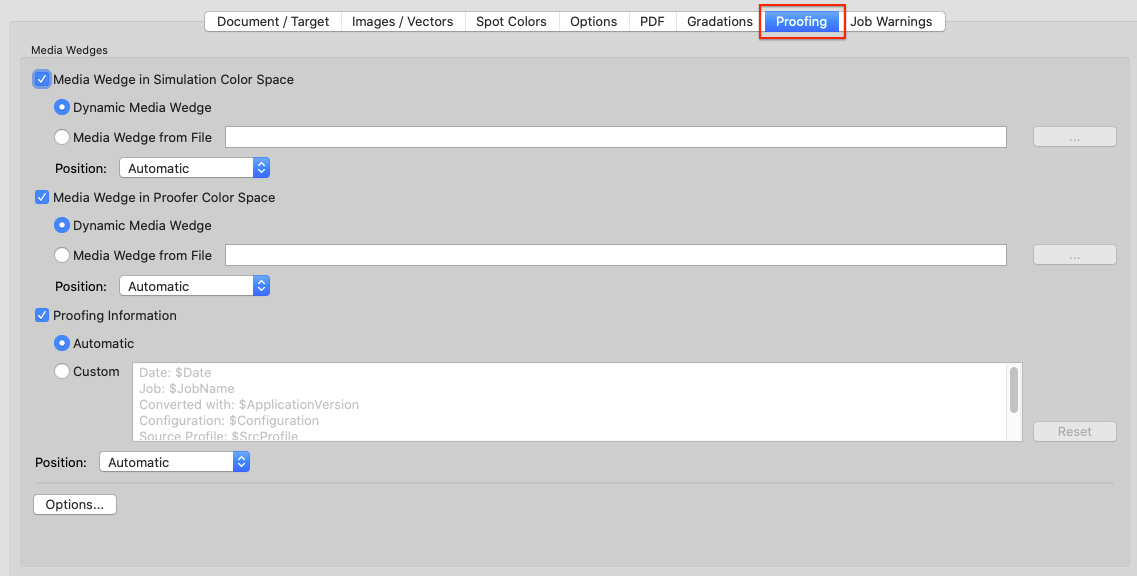
The Proofing tab under Configuration contains all Media wedge settings and the Proofing Information label.

Media Wedges

Two types of media wedges can be used:

  1. Media Wedge in Simulation Color Space: Can be used to determine the accuracy of the proof. This media wedge is converted based on the color management setting defined in the various configuration tabs.
  2. Media Wedge in Proofer Color Space: Allows using a second media wedge that is not color managed. It must be in the color space of the proofer and can be used to determine the stability of the proof printer.

Choose a Media Wedge.The media wedge is added outside the document’s media box to verify the proof. This can either be a dynamic or an external media wedge.

Dynamic Media Wedge: Uses the color space information of the simulation color space and dynamically adds all spot colors of the documents to be processed. The required reference files for measuring the wedges are created on-the-fly by ZePrA. They will be saved in the Folder for Report and other Data folder of the proofing queue that has automatically been set up by the Auto Setup Wizard.

Note: Currently, a maximum of 32 channels is supported for dynamic media wedges.

The reference files for dynamic media wedges contain both the device values (DCS values) and the target Lab values. The target Lab values are also calculated for the spot colors of the job and incorporated into the reference file in addition to the color values of the document color space. This is done according to the settings under Configurations > Options (solid tone only or gradation values as well) and Configurations > Spot Colors.

The measured values obtained can then be immediately compared to the target Lab values (e.g. in ColorAnt/Compare). Use these reference files in appropriate tools, such as ColorAnt’s Measure Tool, for measuring.

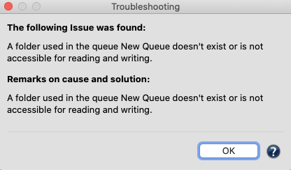
Note: Reference files are not created when the report folder Folder for Report and other Data is missing. If an existing queue is to be used for proofing, it must be verified that the folder for reports exists. If necessary, it must be created manually so that a reference file can be created. If this folder is missing, the reference file cannot be created.​

Reference files are created for each job in the queue and named as follows:

Jobname_DynamicMediaWedgeReferenceSource
Jobname_DynamicMediaWedgeReferenceTarget

If dynamic media wedges are selected for source and target color spaces, two reference files for each job will be created.

Note: If the same job is run again, the reference file will be overwritten. This means that if the spot color patches are changed under Options, a modified reference file is saved, and any previous conversion with the reference file with a different number of patches is lost.
The use of spot colors for the dynamic media wedge can be defined under Options 

Media Wedge from File: Can be media wedges such as the FOGRA, UGRA, Idealliance* or other media wedges. For external media wedges, the corresponding reference file is required to measure the printed wedge. Measurements can be done with any proof evaluation software or with ColorAnt’s Measure Tool.

*The IDEAlliance ISO 12647-7 Control Wedge 2013 is included in ZePrA and available under /Users/Shared/ColorLogic/MediaWedges (Idealliance ISO 12647-7: 2013, 3-Row Digital Control Wedge ® is a registered trademark of the Idealliance).

Note: A separate ColorAnt license is required to use the measurement and comparison features.

Proofing Information: Enabling this checkbox will add text information which are in accordance with ISO 12647-7 such as information about the job, date and time, conversion settings and the software used. The information that will be added to the converted file can be verified and edited in the text field. For editing switch to Custom.

Frame: Adds a frame around the Proofing Information.

Logo: Inserts the logo specified in the Preferences into the Proofing Information.

Position: The two media wedges and the proofing information label can be positioned independently on the converted document. For each of these 3 elements, the user can specify where it should be placed. Positioning options are: Automatic, Bottom Margin, Right Margin, Top Margin, Left Margin. The elements are placed outside the media box of the document according to this setting. This results in an enlarged media box in the converted document. Automatic is suggested as default settings for all 3 elements to make sure that they are placed together on the converted job.

Options: General settings and settings for Dynamic Media Wedges can be defined under Options.

Media Wedge Options

General

Font Size: Defines the font size used for the proofing information label in points.

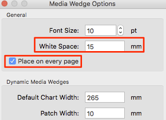
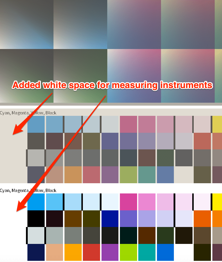
White Space: Allows the placement of margins on media wedges by entering a user-defined distance in mm. By default a white space of 15 mm is added. This ensures that enough white space is added on the left and right of the placed media wedges which some instruments need for correct measuring. The White Space margin applies both to external and dynamic media wedges.
Note: If the external media wedge already has a margin, we recommend entering 0 mm as White Space. As a rule of thumb the white space in millimeters for dynamic media wedges should be at least the size of the Patch Width. The white space of the Media Wedge in Simulation Color Space is color managed whereas the white space of the Media Wedge in Proofer Color Space is not.

Place on every page: For multi-page PDF files media wedges can be placed on each page. By disabling the checkbox media wedges will be placed on the first page of the PDF only.

Dynamic Media Wedges

Defines the Default Chart Width, the Patch Width and the Patch Height of the dynamic wedge.

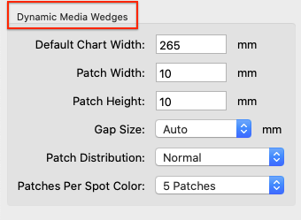
Gap Size: To separate individual patches. Select the width in mm.

Patch Distribution: Defines the distribution of patches on the media wedge.

  • Randomize: Color patches are distributed randomly.
  • Normal: Color patches are distributed as specified in the reference file.
  • Sorted: Color patches are sorted from light to dark.

Patches per Spot Color: Defines whether spot colors are to be used in the dynamic media wedge and, if so, whether tints are to be used.

  • None: No spot color is added to the dynamic wedge.
  • Solid Tone: Only the solid tone of each spot color in the job is used in the dynamic wedge.
  • 3 Patches: Uses the following patches for each spot color: 100%, 70%, 40%.
  • 5 Patches: Uses the following patches for each spot color: 100%, 70%, 40%, 20%, 10%.

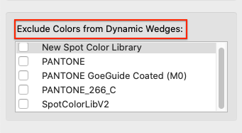
Exclude Colors from dynamic wedges: Spot colors are used in documents for various reasons besides printing purposes, e.g. to illustrate the DIE cut lines, or varnish, braille or other non printing elements. Obviously, those colors are not to be used in the dynamic media wedge. To avoid using them in media wedges, create a library (or more if needed) containing all spot colors to be excluded and select it (or them) from the list under Exclude Colors from dynamic wedges. This list contains all spot color libraries managed by ZePrA. Enable the checkboxes of only those libraries which contain the colors to be excluded.

The selected libraries containing the colors to be excluded are also applied to spot colors of external media wedges. Typically, if the Document Color Space is Multicolor, ZePrA assignes the channels of the Document Color Space to the channels of the media wedge. This is intended in most cases, e.g. if a 7C media wedge with generic channel names is used for a 7C Document Color Space in such a way that the channels are associated. However, this is not intended in case a spot color White is to be used as 5th channel and the 5th channel in the Multicolor profile of the Document Color Space is called Orange (for example). To retain the white spot colors an exclusion library which contains White as non-printing color can be selected.

Video Tutorial

How to Use the Proof Evaluation Tool in ColorAnt in combination with ZePrA

Learn step-by-step how to use the Proof Evaluation tool in ColorAnt for the evaluation of a proofing media wedge created with ZePrA. In this example, we will be demonstrating the special feature of ZePrA to create a dynamic media wedge using process and spot colors and how to use the supplied reference data from ZePrA for evaluation of a Contract Proof.

ZePrA | Troubleshooting

Troubleshooting

Detect and resolve errors

Overview

To prevent errors and problems when processing files, ZePrA checks configurations and hot folders as well as settings and licenses.

If errors or problems are detected, an error message appears in the lower left of the ZePrA window.

If you click on this message, the error is displayed. If several errors are detected, a list of all errors is displayed.

Another click on the corresponding message opens the Troubleshooting dialog, which lists possible solutions to the problem found, which can then be applied to resolve the error.

Causes of errors

Errors can occur, for example, if certain profiles (or spot color libraries) are used in a configuration without embedding them in the configuration, and this configuration is then transferred to a computer on which these profiles (or spot color libraries) are not available. It is then not possible to process files with this configuration.

But certain combinations in the settings can also cause problems.

ZePrA therefore checks:

  • Configurations
  • Settings
  • Hotfolder (all required folders must be available)
  • Profiles (all required profiles must be available on the computer)
  • Gradation curves (all required gradation curves must be available on the computer)
  • Licenses (all required licenses must be available on the computer, depending on the job this can be SmartLink, Multicolor, spot color or SaveInk licenses)
  • Spot color libraries (all required spot color libraries must be available on the computer)

Troubleshooting

In the Troubleshooting dialog, the identified problem is described and options for solving the problem are suggested.

Some problems can occur in multiple configurations and can be solved immediately for all affected configurations, for example, when using the Perceptual Rendering intent in combination with SmartLink.

Click on the message to open the Troubleshooting dialog. Here, by selecting the Solve the issue automatically checkbox, you can switch all affected configurations to Standard Compression without having to change each configuration individually.

CoPrA | DeviceLink Iterate

Iterate

Improve DeviceLink profiles

Iterate

Overview

An existing DeviceLink profile can be optimized based on measured color values by using a test chart of your choice (can be created with ColorAnt/Custom Chart, see video turorial below). The iteration​test chart needs to be converted from source to target profile using the original DeviceLink profile and printed on the target printer. The measured color values of the printed test chart are then used to improve the conversion in order to achieve lower color differences and a more accurate reproduction of the source color space. Based on the measured values, it is automatically determined whether the target values are reached (which are determined by the source and target profiles) and a correction is made for deviations. Iteration is therefore particularly useful in proofing situations with absolute or relative colorimetric rendering intents. Perceptive rendering intents can also be used as a special feature of DeviceLink iteration in CoPrA. The iteration calculates a new DeviceLink profile based on the original DeviceLink profile and the measured values. The new profile can be reinserted for iteration until the desired result is achieved.

Iteration for Proofing and Production Printing

Iteration is a great method to get the best possible match for proofing. Proofing uses absolute colorimetric rendering without color exceptions. However, in digital production printing, perceptual rendering methods and color exceptions are used to keep colors pure. Nevertheless, there might be an interest to optimize the colors by iteration measurements (Note: It is not always recommended to do so, especially as out-of-gamut colors cannot be optimized).

Using the Iterate tool, it is possible to iterate data for production printing while retaining exceptions during the iteration process. CoPrA recognizes exceptions and rendering settings from the selected reference DeviceLink profile and retains them (only if the selected DeviceLink is a ColorLogic profile). A checkbox is shown when exceptions are used. By default, the checkbox is enabled. 

Notes

  • Iterate requires a DeviceLink license.
  • The test chart must match the color space of the source profile. 
  • Out-of-gamut colors of the original color space can only be improved to a limited extent. 
  • In proofing situations, the gamut of the target color space ought to be larger than that of the source color space, which makes iteration particularly interesting for DeviceLink profiles in proofing applications.
  • Iterations cannot be repeated arbitrarily due to fluctuations in print output, print material and the reproducibility of measuring instruments. More than 2-3 iterations are usually not necessary and not recommended.
  • Only DeviceLink profiles whose source and target profiles are available and referenced in the DeviceLink profile can be iterated. A warning is issued if the required source and target profiles are missing.
  • Third-party DeviceLinks that reference the used source and target profiles can also be iterated.
  • DeviceLinks that use color Exceptions and perceptual rendering options (such as conversion and separation profiles) can be iterated as well, but it should be done with care and it can only be done for ColorLogic DeviceLink profiles.
    Iteration allows the target values to be reached more accurately, which can result in a loss of channel purity if no exception settings are retained. Perceptive rendering intents require an interpretation of the measurement data, which can lead to slight shifts during iteration.
  • With a DeviceLink and a Multicolor license Multicolor DeviceLinks can be iterated, too.

Procedure

Procedure

Procedure

  1. Select Iterate in the sidebar or DeviceLink Iteration in the Navigation menu.
  2. Select the DeviceLink profile that you would like to iterate from the drop-down menu. Make sure that both the source and target profiles used in the DeviceLink are available in the ICC profile folder of your operating system, as CoPrA needs those to calculate the iterated profile. 
  3. Convert the test chart to be used for iteration with the DeviceLink profile and print it on the printer using the same settings as for the profiling test chart for this printer. The test chart can be converted using CoPrA’s Image Conversion tool.
    
Note: Use a test chart that contains the colors you would like to optimize. Typically, test charts with few color patches will suffice, but those patches must reflect the colors to be optimized. Therefore, using large profiling test charts is not required. Instead of using large test charts, use charts that can also be used to update profiles (see ColorAnt/Custom Chart tool). The color space of the test chart must correspond to the color space of the source profile of the DeviceLink.
  4. Measure the printed test chart in ColorAnt, save the measurement data and open it in CoPrA’s Iterate tool, either via drag-and-drop or via the Load button. Alternatively, click Measure and measure the test chart with CoPrA’s integrated Measure Tool.
  5. Depending on the selected DeviceLink profile and its settings, the checkbox Use same Settings from DeviceLink including exceptions will be activated or grayed out. It is activated for ColorLogic DeviceLink profiles that use Exceptions. If the DeviceLink is not a CoPrA profile or if it does not use exceptions, – which should be the default setting for proofing, – the checkbox is grayed out.
    Note: If the checkbox Use same Settings from DeviceLink including exceptions is deactivated, then all Exceptions are deactivated in the iterated DeviceLink profile.
  6. If you disable the checkbox Use same Settings from DeviceLink including exceptions,  then all exceptions are disabled in the iterated DeviceLink profile.
  7. Click Next to get to the Save dialog Format, Size and Further processing.
    Notes:
    a) The Default Template uses an option to add the iteration count number to each iterated DeviceLink.
    b) Size: It is recommended to select Auto because size matters for iteration. The Auto feature ensures that the highest precision is always used when creating the iterated DeviceLink.
    c) The newly created DeviceLink will have a more accurate color rendering for most in-gamut colors compared to the original DeviceLink profile. You can now use it in exactly the same way as the original one or use it for further iterations..
  8. If you would like to further optimize the DeviceLink, proceed as described above. However, select the previously iterated DeviceLink instead of the original one. Now convert the original test chart with the iterated DeviceLink (do not take the already converted test chart from point 3!) and use the measurement data of this printout to calculate a further optimized DeviceLink profile.

Format, Size and Further Processing

In the last step of profile creation, assign a Name and choose the Format and Size of the profile (see screenshot).

Name: Type in a Name for the profile.

Templates: Allows to select and combine name components from a list of options and save them as custom templates. The last selected template is used when creating new profiles, so the naming of profiles is automated.
Available naming options depend on the current profile type and include Date, Date/Time, Measurement data file name, Source and Target profiles, Name of the current preset and others. Each name component can be added at a user-defined position under Template (the position is selected with the mouse pointer). The Example section below shows the resulting name. Additionally, user defined text can be added at any position within the Template field.

Format: Define the Format of your profile. An ICC format in accordance with specification v2 is recommended as a basic setting, however, the newer format ICC v4 can also be chosen. In this case, please ensure that your programs support this format.
Note: ColorLogic products handle and use ICC v4 profiles consistently and correctly.

Size: The setting Large is recommended. The size specifies the number of grid points in the profile and determines the amount of disk space required for the generated profile. Small profiles should only be used for test purposes. Very Large profiles can slow down further processing in subsequent programs. Additionally, some programs are not able to handle very large profiles.

Further processing

Create Profile Report: Recommended to activate. The PDF report provides an overview of the quality of the profile based on statistics, diagrams of gray balances, gradients and gamut representations as well as evaluation results and details of the DeviceLink iteration.
Under Preferences, the Default save path for the reports and the Default report format can be selected. If XML is selected as the format, the corresponding XSD files will be created automatically as well.

Save Preview Profile: Is only available in Multicolor printer profiling. By activating this checkbox an ICC preview profile will be created in addition to the printer profile. It can be used as a soft proof profile in Adobe Photoshop.
Notes: Preview profiles are only suitable for proofing purposes. Either a preview profile or a CMYK profile can be created in one profiling step, but not both.

Embed profiles: Physically incorporates the used source and target profiles into the DeviceLink. This function is tricky and only recommended if the DeviceLink has to be transferred to a computer which does not have the required source and target profiles. It was implemented mainly for use with certain RIPs which only accept DeviceLinks with embedded source and target profiles.

Save: Creates the printer profile and saves it in the folder Profiles (macOS) or Color (Windows), (macOS: /Users/Username/Library/ColorSync/Profiles, Windows: C:/Windows/System32/spool/drivers/color). Demo and encrypted profiles will be saved in a different location only relevant for ColorLogic applications.

Note: CoPrA-SP profiles are stored in the ColorLogic subfolder Licensed-Profiles.

Profile Reports

Profile reports can be created for Printer or DeviceLink profiles. To do so, activate the checkbox Create Profile Report in the last step of the profiling or, when updating profiles, the checkbox Create Profile Comparison Report.

Depending on the type of profile the report contains various statistical data, such as statistics about profile precision (Integrity, Precision, Black Point, White Point etc.), graphic representations of curves and gamuts (Gray Balance, Gradients etc.), conversions of test images, separations and color patches to evaluate the smoothness or the purity of colors. All this facilitates the detection of artifacts that may be present.

Profile reports can be created at any time in Batch Overview or in Profile Manager which, by the way, is not restricted to ColorLogic profiles.

Under Preferences you can define some basic settings for the creation of the profile report, such as the file location, the report format (PDF or XML) or the DeltaE method (dE76 or dE2000).

Note: If a profile comparison report is created when updating a profile, the measurement data obtained from the update test chart will be compared to the data of the original profile (reference profile).

If the checkboxes Brightener Compensation or Measurement Correction have been activated, the data of the original profile will not be compared to the measurement data from the update test chart but to the data modified by these options.

Verifying the optimization

Verifying the optimization

ColorAnt can be used to verify a successful optimization. First create a “Lab Reference” to compare the measured values of the printouts to the values of the DeviceLinks. Use the ICC Transformation tool to create the Lab reference values by using the device values of the original test chart and the source profile and rendering intent of the DeviceLink. These Lab reference values now serve as comparison values after each application of the iterated DeviceLinks on your test chart. Compare the measurements of the iteration with the “Lab Reference” using the Compare tool in ColorAnt. 

You will notice that in-gamut colors of the iterated DeviceLink are closer to the Lab reference than those of the original DeviceLink.

Video Tutorial: How to create a test chart for iteration

Video Tutorial: How to iterate

CoPrA | Preferences

Preferences

Define basic settings

Preferences

View

Choose the tool that opens at startup. Allows quick access to the preferred tool. By activating the checkbox Do not display informational popups graphical information about tools of the Sidebar will no longer be displayed. However, tool tips for features will still be shown.

Profiles

Profiles: Select the location for your profiles. By default profiles are stored in the system profile folder (except for CoPrA SP licences). To store your profiles in a different location, for example a network folder, simply activate the checkbox Custom profile folder and specify the storage path.
Subfolders for the various profile classes and color spaces are created automatically.

Note: Profiles which are not stored in the system profile folder may not be available for other programs.
For Mac users: Create a subfolder in the ColorSync profile folder to store all profiles created by CoPrA in one place. These profiles will still be accessible for all programs using ICC profiles.

Overwrite existing preview profiles automatically: Preview profiles can be created when creating DeviceLinks or Multicolor profiles but they can also be created in Batch Overview or Profile Manager. By activating the checkbox Overwrite existing preview profiles automatically existing preview profiles will be overwritten without warning.

Share with ZePrA

Due to the close linkage of CoPrA and ZePrA, DeviceLink profiling settings specified in CoPrA can be used by ZePrA to create profiles required for the conversion of PDF files on-the-fly.

With CoPrA 6 and higher the settings are accessible via a shared folder which has the advantage that CoPrA and ZePrA do not need to be installed on the same computer. The shared folder must simply be accessible by both ZePrA and CoPrA, either over the network, a shared local folder or the cloud.

Share CoPrA Settings with ZePrA Auto Import Folder: Enable the checkbox to share CoPrA’s settings with ZePrA and select ZePrA’s Auto Import folder.

Note: If the checkbox is enabled and the Preferences dialog closed with OK an information message will appear repeatedly asking the user if all shared presets should now be copied to the defined Auto-Import Folder.

ZePrA’s Auto Import Folder
Files (such as ICC profiles, configurations, spot color libraries, gradations or SmartLink settings) that are moved or copied into the
Auto Import folder are transferred to ZePrA’s internal dataset and can then be used by ZePrA.
When the file in the Auto Import folder is replaced by a newer version, it will be updated in ZePrA’s internal datasets as well.
Note: If a file in the Auto Import folder is deleted, it is not deleted in ZePrA’s internal dataset. For example, if a SmartLink setting has been deleted in the Auto Import folder, it is still available in ZePrA’s internal dataset and if this setting is deleted in ZePrA’s dataset, it is still available in the Auto Import folder.

Profile Manager Options

The default 3D gamut viewing method of CoPrA 9 and higher is based on an axis ratio of 1:1:1. This means that the axis ratio of L to a+ (a-) as well as to b+ (b-) is identical. Up to CoPrA 8, the L axis was twice as long in ratio (see screenshots).

To use the 2:1:1 axis ratio view used in CoPrA 8 or older, change the 3D Gamut Axes Ratio (L:a:b) setting.

Please note that the 3D gamut view options also affect the gamut view in the Printer Profiling tool on the Color Generation tab.

Report Creation

Default save path: Reports (in PDF, XML and XSD format) are automatically saved in the folder specified here.

Default report format: Select the preferred file format for the report, either PDF or XML. If XML is selected as the format, the corresponding XSD files will be created automatically as well.

Default DeltaE Method: Determines the DeltaE method to calculate color differences for profile reports (dE76 or dE2000).

Open profile reports automatically with default viewer: If enabled, the profile report will be opened and displayed by the default PDF or XML viewer immediately after its creation.

Report Customization

Here you can enter a subtitle or add your own company Logo to the profile report. By default CoPrA’s icon is used.

Protected Mode

The Protected Mode allows to lock and protect all custom settings. If activated – with or without a password – changing a selected profiling setting is denied. This feature proves to be practical if multiple operators in an organization are creating profiles and only a defined set of settings should be used instead of every operator using his own settings. Once the protected mode is activated, options in the Preferences are disabled and importing and exporting of settings is denied.

If you need stricter permissions, the Protected Mode can be used with a password.

Set Password: Enter a secure password and confirm by entering it a second time. If a password has been set, it must be entered each time the protected mode is to be deactivated. To remove or change the password, click Reset Password.

Note: Remember your password well or keep it in a safe place!

ZePrA | Push 2 ZePrA

Push-2-ZePrA

Process PSD files directly from Photoshop

What is Push-2-ZePrA ?

Push-2-ZePrA is an Adobe Photoshop extension that allows color converting an image file selected in Photoshop with ColorLogic’s color server ZePrA from Photoshop. Depending on the color server settings high quality color conversions with DeviceLink profiles will be performed leading to better color rendering of images than typical color conversion with Photoshop. Even spot colors can be converted if the selected ZePrA configuration is set up accordingly. The converted file will be opened up in Photoshop so that you do not need to leave Photoshop in order to get the best possible color converted images.

Push-2-ZePrA System Requirements

System Requirements for Push-2-ZePrA version 3

  • macOS 10.15 and higher
  • Windows 10 and higher
  • Adobe Photoshop CC 2021 and higher.
  • ZePrA 11
  • Supported file formats: TIFF, JPEG, PSD and PSB
  • Unsupported file formats: PNG, PDF and EPS
  • On macOS systems with M1/M2 Apple Silicon processors make sure that you start Photoshop via Rosetta. The Push-2-ZePrA extension does not run natively on M1/M2 chips.

System Requirements for Push-2-ZePrA version 1 and 2

  • macOS 10.13 and higher
  • Windows 8 and higher
  • Adobe Photoshop CC 2017 and higher.
  • Supported file formats: TIFF, JPEG, PSD and PSB
  • Unsupported file formats: PNG, PDF and EPS
  • On macOS systems with M1/M2 Apple Silicon processors make sure that you start Photoshop via Rosetta. The Push-2-ZePrA extension does not run natively on M1/M2 chips.
  • ZePrA 9 and higher/Push-2-ZePrA v2 and higher: The 2nd edition of Push-2-ZePrA has network capability. This eliminates the need for ZePrA to be installed on the same computer as Photoshop.

Note: Push-2-ZePrA is integrated with a 1-client license in ZePrA XL and XXL. Additional 5-client or 10-client multi-user licenses can also be purchased. For ZePrA Entry, Basic and L, the Push-2-ZePrA Photoshop extension single and multi-user licenses can be purchased as add-ons.

Installation
  1. Use the installer for macOS or Windows for your respective operating system.
  2. Close Photoshop before installation and follow the easy-to-use installer.
  3. Once installed, start Photoshop, go to Window/Extensions and select Push-2-ZePrA to open the extension.

Note: The installer on macOS systems will take an additional step to prepare Photoshop. Hence Photoshop must be closed before installation. The warning message is displayed twice. Just click the Allow button twice to install.

Using Push-2-ZePrA locally

Using Push-2-ZePrA locally

Configuring the Push-2-ZePrA clients in Photoshop:

  1. Once the Push-2-ZePrA extension is installed, start Photoshop, go to Windows/Extensions and select Push-2-ZePrA to open the extension.
  2. Click the Gear icon. There are two ways to connect to the ZePrA server: locally or remotely. If your Photoshop/Push-2-ZePA installation is on the same computer as the installed ZePrA color server you should always prefer the ZePrA Local option as this is much faster than communicating via the network. Click ZePrA Local.

  3. Under ZePrA Path navigate to the ZePrA.app on macOS or zcmd.exe on Windows and select it.
  4. Define your Local Output Path (where converted files are to be saved) and click the Home button. You can then immediately use the extension.

Using Push-2-ZePrA locally

When ZePrA is installed on the same computer as Photoshop:

  1. In Photoshop, open the image to be color converted.
  2. Click on the Push-2-ZePrA extension.
  3. On the Home tab select a ZePrA Configuration from the drop-down menu. The drop-down list will show all the configurations set up in ZePrA.
    Note: A search option is available here, where any number and letter can be entered and only the configurations containing these numbers and letters are listed in the drop-down menu below. This makes it easier to search for specific configurations, especially if the list of configurations in ZePrA is very long.
  4. Choose a configuration that fits your requirements in terms of Target Color Space and retaining of Photoshop Layers. This information is shown below the drop-down menu and picked from the selected configuration.
  5. Click Convert.
  6. After a few seconds, the progress will be displayed, and the converted file will be opened up in Photoshop.
  7. Output folder for local use: Converted files are always saved in the same location as the original file and the configuration name will be appended to the original file name.
    Notes: If the original file has been edited or copied in Photoshop without saving, a temporary file needs to be created by Push-2-ZePrA. The edited and the converted temporary files are saved in the output folder defined under Local Output Path.
    If the original file is located in a read-only folder, the user will be asked if the converted file is to be saved in the output folder defined under Local Output Path.

Note: ZePrA’s Command Line Interface (CLI) is used for the conversion but not the ZePrA application itself. Therefore, you won’t find any of the images that have been converted via the Push-2-ZePrA extension in ZePrA’s Overview or hot folders.

    Using Push-2-ZePrA over the network

    Connecting Push-2-ZePrA with ZePrA over the network

    Note: Requires ZePrA 9 or higher and Push-2-ZePrA v2 or higher.

    Push-2-ZePrA is network capable from version 2. This eliminates the need for ZePrA to be installed on the same computer as Photoshop.

    ZePrA 9 and higher have an integrated Push-2-ZePrA remote server, while the Push-2-ZePrA extension acts as a client application that can access ZePrA from a remote Photoshop installation over the network.

    Therefore, several users who have the extension installed in their Photoshop application can remotely access the same ZePrA server. The Photoshop clients can thus be used on different computers, but also under different operating systems than the ZePrA server.

    Establishing a connection

    Configuring the ZePrA server:

    1. Open the Server Settings from the Tools menu in ZePrA.
    2. Specify the IP address of the computer ZePrA is running on and set a Port. See your system administrator for IP and port information. You will need to enter both the IP address and the port number in the Push-2-ZePrA extension on all client computers.

    3. Click Start to activate the server. The Status changes to Server is running and the License Status indicates the number of licenses in use as well as the number of available licenses.
    4. Stop closes the server and the extensions will no longer work. Closing ZePrA does not stop the server service but shutting down the computer will. So when restarting the computer make sure to restart the ZePrA server in the Server Settings dialog so that the extensions can access it.

    Note: Under macOS the IP address of the computer can be found in the System Preferences/Network settings. Under Windows the IP address can be found under Settings > Network & Internet > Status > View hardware and connection properties.

    After a ZePrA update, stop the server and restart both ZePrA and the server. This way the newest version of the server will be used.

    Configuring the Push-2-ZePrA clients in Photoshop
    1. Install Push-2-ZePrA and open it in Photoshop.
      Note: On Macs with Apple Silicon M1 chip make sure to start Photoshop with Rosetta – see System Requirements.
    2. Click the Gear icon.
    3. There are two ways to connect to the ZePrA server: locally or remotely. If your Photoshop/Push-2-ZePA installation is on the same computer as the installed ZePrA color server you should always prefer the ZePrA Local option as this is much faster than communicating via the network. If your Photoshop/Push-2-ZePA installation is on a different computer, use the ZePrA Remote option.

    4. To use the ZePrA Remote option, enter the previously defined ZePrA server settings (Server IP Address and Server Port Number) under ZePrA Remote and click the Connect button under Test Connection. The connection status is displayed.
    5. When the connection is successfully established, define your Local Output Path (where converted files are to be saved) and click the Home button. You can then immediately use the extension.

    Note: If all available licenses are linked with the ZePrA server, additional Photoshop extension users will not be able to connect to the ZePrA server. The licenses are linked to the ZePrA server on a first come first served basis.

    Note: In order to use the Photoshop extension, the ZePrA remote server must be running. Once the server has been started in ZePrA, it will run even if the ZePrA application is closed later on. Only when the computer is shut down, the server is also shut down and must be restarted in ZePrA after the computer is restarted.

    Use the Question mark icon to access the Push-2-ZePrA online help page, and the Exclamation mark icon to get the version numbers of the extension and the ZePrA Remote server.

    Using Push-2-ZePrA remotely

    When ZePrA is accessed over the network:

    1. Open up an image in Photoshop to be color converted.
    2. Click on the Push-2-ZePrA extension.
    3. Select a ZePrA Configuration from the drop-down menu. The drop down list will show all the configurations set up in ZePrA.
      Note: A search option is available here, where any number and letter can be entered and only the configurations containing these numbers and letters are listed in the drop-down menu below. This makes it easier to search for specific configurations, especially if the list of configurations in ZePrA is very long.
    4. Choose a configuration that fits your requirements in terms of Target Color Space and Photoshop Layers retaining. This information is shown below the drop-down menu and picked from the selected configuration.
    5. Click Convert.
    6. After a few seconds, the progress will be displayed, and the converted file will be opened up in Photoshop.
    7. Output folder for network use: Converted files and temporary files are always placed in the output folder defined under Local Output Path and the configuration name will be appended to the original file name.
      Note: If the original file is located in a read-only folder, the user will be asked if the converted file is to be saved in the output folder defined under Local Output Path.

    Note: ZePrA’s Command Line Interface (CLI) is used for the conversion but not the ZePrA application itself. Therefore, you won’t find any of the images that have been converted via the Push-2-ZePrA extension in ZePrA’s Overview or hot folders.

    Recommendations and Troubleshooting

    Best Practices

    For image conversions, we recommend setting up Direct Color Conversion configurations in ZePrA with the help of the Auto Setup Wizard. With a direct conversion from the image color space to the Target Color Space, double conversions are avoided. It is not recommended to use a Normalize and Convert queue as this can lead to converting the image two times (a double conversion – from the image color space to the Document Color Space and then to the Target Color Space), which typically is not wanted for image conversions.

    For any changes in terms of PSD or TIFF file layers handling, color conversion or spot color conversion, please adjust the appropriate ZePrA configuration in the ZePrA color server. The Push-2-ZePrA Photoshop extension uses the configurations, but editing configurations is not supported.

    Error Handling

    When working with the Push-2-ZePrA extension potential issues might happen:

    1. When updating Photoshop to a newer version, the Push-2-ZePrA extension may no longer be loaded. In this case, it is recommended to re-install the Push-2-ZePrA extension.
    2. The Push-2-ZePrA Photoshop extension version 3 is only executable with ZePrA 11.
    3. The maximum file size that can be processed via the remote connection using the zcmdServer of ZePrA 10 is 512 MB. Larger files can be processed directly via ZePrA Queues.
    4. The zcmdServer included in ZePrA 11 allows the processing of image files up to a size of 2 GB.
    5. Please do not use the zcmdServers of ZePrA 10 and 11 at the same time. Make sure the server in ZePrA 10 is stopped (click the Stop button in the Server Settings dialog). After that open the Server Settings dialog in ZePrA 11 and click on Start to activate the zcmdServer of ZePrA 11.
    6. Select the proper file for conversion: When several images are open in Photoshop keep in mind that only the selected, active document will be converted with Push-2-ZePrA.
    7. Incomplete conversions: When clicking the Convert button it may take a few seconds until the image is converted. During processing (the progress will be displayed), do not close the Push-2-ZePrA extension nor minimize Photoshop. This will immediately stop the conversion.
    8. Restricted folders and locations: A warning message appears when trying to save a file in a restricted location. If the selected location (folder) is read-only (for example, the application folder of an operating system), a warning message is displayed prompting you to cancel the conversion or save the converted file to the Local Output Path.
    9. Troubleshooting job warnings: An error message with the selected configuration appears. In such a situation, check the corresponding configuration in the ZePrA application and check for the cause of the error. It may be that the image file and the setting in the configuration do not match. In such a case, it is suggested to convert the image file in the ZePrA application with the same configuration used in the Push-2-ZePrA extension. The same job warning message may show in ZePrA. Troubleshoot the issue and change the settings in the ZePrA application, until the file conversion works as desired. Once the configuration has been saved in ZePrA go back to the Push-2-ZePrA extension, close it and reopen the extension to update the list of configurations and settings and convert the file in Photoshop again.
      Note: Push-2-ZePrA supports the same image file formats as ZePrA, e.g. TIFF, JPEG, PSD and PSB. Unsupported file formats, such as PNG, PDF or EPS, will generate file format errors.
    10. Changes and updates to configurations: When changes or updates to ZePrA configurations have not been applied in the Push-2-ZePrA extension, make sure that the edits have been saved in ZePrA before heading to the Photoshop extension. Then close the extension and start it again so that it refreshes the list of configurations and their settings.
    11. Support for prior ZePrA versions: ZePrA versions prior to v9 are not supported. The extension may show the settings of configurations from older ZePrA versions, but will not convert files. We do not recommend selecting prior ZePrA versions with the extension and will not be supporting prior versions in future releases.
    12. Avoid special characters in configuration names: characters such as | < > * ? / \\ : in configurations names with ZePrA. While ZePrA will handle such characters the Push-2-ZePrA extension does not.