ZePrA | Configuration | Options


File Processing Options
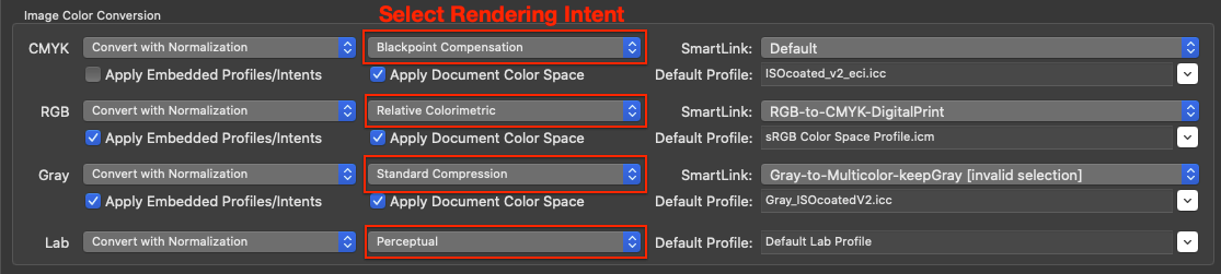
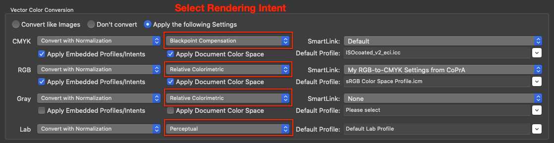
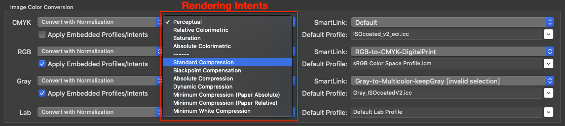
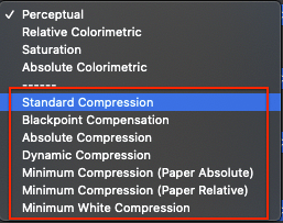
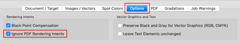
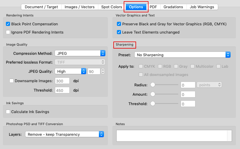
Rendering Intents
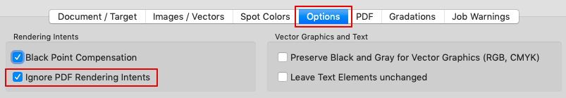
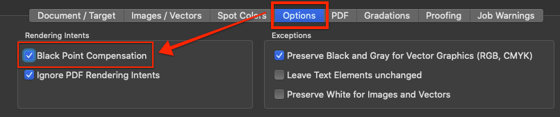
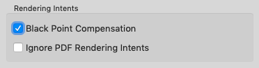
Black Point Compensation: Enabled by default. Ensures that high-quality color conversion is performed without detail losses in the shadows when using the relative colorimetric rendering intent. This is especially important in PDF documents as relative colorimetric with black point compensation is not supported in PDF files before PDF 2.0. PDF 2.0 and higher does support black point compensation – see section below.
Typically the rendering intent to be used when converting or viewing PDF files is defined together with the embedded ICC profile of each object and is set by the PDF authoring application. In such applications, the default rendering intent is usually set to relative colorimetric with black point compensation but in older PDF files – due to the lack of support – this becomes relative colorimetric (without black point compensation) leading to detail losses in the shadows after conversion. For that reason black point compensation is a separate option in the preferences of many PDF applications.
Tip: If you would like to color convert images or PDF documents for proofing using the relative colorimetric rendering intent (for example because you are using the same paper stock for production and proofing) then disable the Black Point Compensation checkbox.
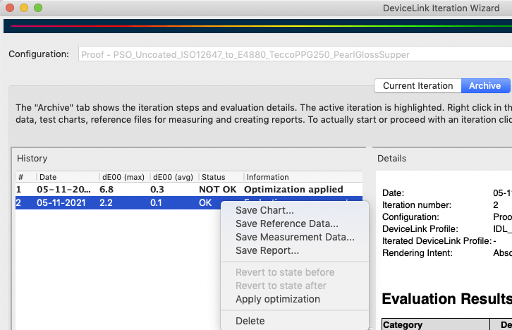
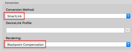
Note: If the Black Point Compensation checkbox is disabled, all color conversions done with the relative colorimetric rendering do not apply black point compensation which may result in plugging of shadows. To avoid this when converting from Document to Target Color Space use SmartLink in combination with Black Point Compensation.
Black Point Compensation with PDF 2.0 files
Modern PDF 2.0 files support black point compensation in combination with the relative colorimetric rendering intent. Black point compensation in PDF 2.0 can have three states: On, Off, Default. Default means that application specific settings are used, e.g. whatever is defined in ZePrA.
- If the Black Point Compensation checkbox is enabled for the processing of a PDF 2.0 file, black point compensation will be applied to all objects of the PDF (such as images, vectors, text, shadings) with relative colorimetric rendering for the states on and default. Black point compensation will not be used for objects with the state off.
- However, if both checkboxes Ignore PDF Rendering Intents and Black Point Compensation are enabled then black point compensation will always be used.
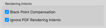
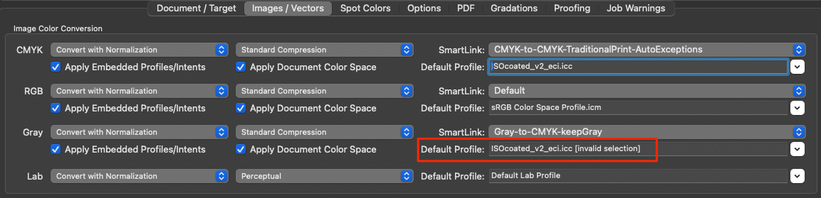
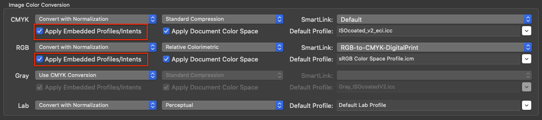
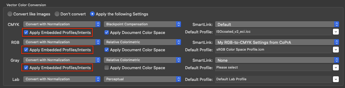
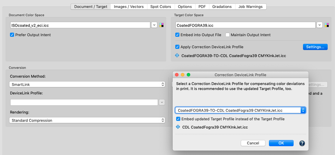
Ignore PDF Rendering Intent: Activating the checkbox Apply embedded profiles/intents in the Images/Vectors tab considers the embedded ICC device profile as well as the rendering intent embedded in the PDF file. If Ignore PDF Rendering Intents is disabled, which is the default setting in ZePrA, the rendering intents defined in each PDF document for each object are used while those defined in the Images/Vectors tab are ignored. This option only applies to PDF files. For image files (PSD, JPEG, TIFF), the rendering intents defined in the Images/Vectors tab are always used.
Enabling the checkbox Ignore PDF Rendering Intents prevents the rendering intent of the PDF file from being used, giving the priority to the rendering intents which have been preset in ZePrA under Images/Vectors. Note that in this situation, the rendering settings are no longer compliant with PDF/X rules.
Image Quality (ZePrA 12 and lower)
TIFF, JPEG, PSD, or PSB image formats are processed in ZePrA the same way as image data of a PDF file.
ZePrA supports images with 8 bit and 16 bit color depth. The color depth of the input data is preserved in conversions unless TIFF, PSD or PSB files are saved as JPEG files under Options/Image Quality. This results in a color depth of 8 bit since only 8 bit is possible in JPEG files.
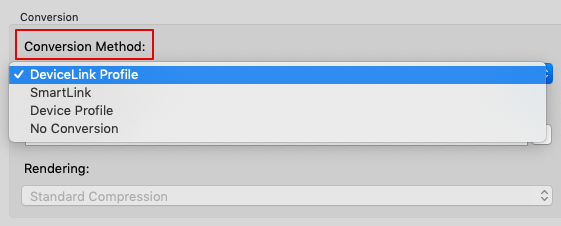
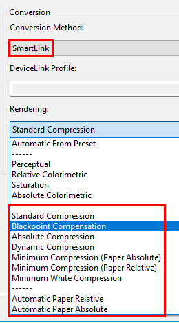
Compression Method: Four compression methods can be used for the color conversion of images:
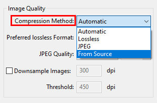
Automatic: Images of PDF files can use a variety of compression methods. The Automatic method typically ensures that all existing image formats and compression methods are preserved. The only exception is that JPEG2000 compressed images of PDF files are written as lossless ZIP compressed images.
This improves interoperability with various PDF workflows and viewers.
Lossless: Saves the image file in either PSD or TIFF format. JPEG data compressed into a PDF file is converted to ZIP. Multicolor files cannot be saved as JPEG.
JPEG: JPEG compression converts TIFF and PSD files to JPEG as well as uncompressed or ZIP compressed data of PDF files.
From Source: Ensures that all existing image formats are preserved, neither the color depth, type nor compression of the input data are changed.
Note: ZePrA does not support JPEG2000 image file formats such as *.jp2, *.jpf or similar.
Downsample Images: Changes the resolution of images. Specify the required resolution in dpi.
Threshold: Specifies the resolution from which images should be downscaled, for example, to optimize data for display on the Internet, to adjust the resolution for printing, or to avoid unnecessary resizing.
Note: ZePrA uses the “Catmull Bicubic Interpolation” method to compensate for the potential loss of sharpness that may occur when images are scaled down.
Tip: The bicubic (sharpen) interpolation method of Photoshop can produce sharper images than ZePrA, but unlike ZePrA it shows noticeable artifacts. As described under Sharpen, the image downscaling and sharpening functions can be combined in ZePrA, in which case ZIP compression is used for images.
JPEG Quality: Allows to define the quality of JPEG compression for pixel images and JPEG compressed images within PDF files. The compression rate is set to High by default, which can result in a larger file after color conversion for maximum compressed JPEG images.
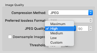
Select one of the four predefined quality levels or determine an individual compression factor with Custom using the percentage.
Tip: ColorLogic recommends using the default setting High 90%.
Ink Amount
Calculate ink amount in converted file: Enable this option to add the section Ink Amount to the Job Report (accessible by right-clicking on a processed job in the Overview). It provides the calculated amount of ink for each channel and processed job.
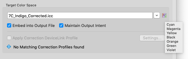
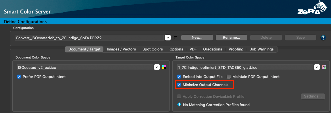
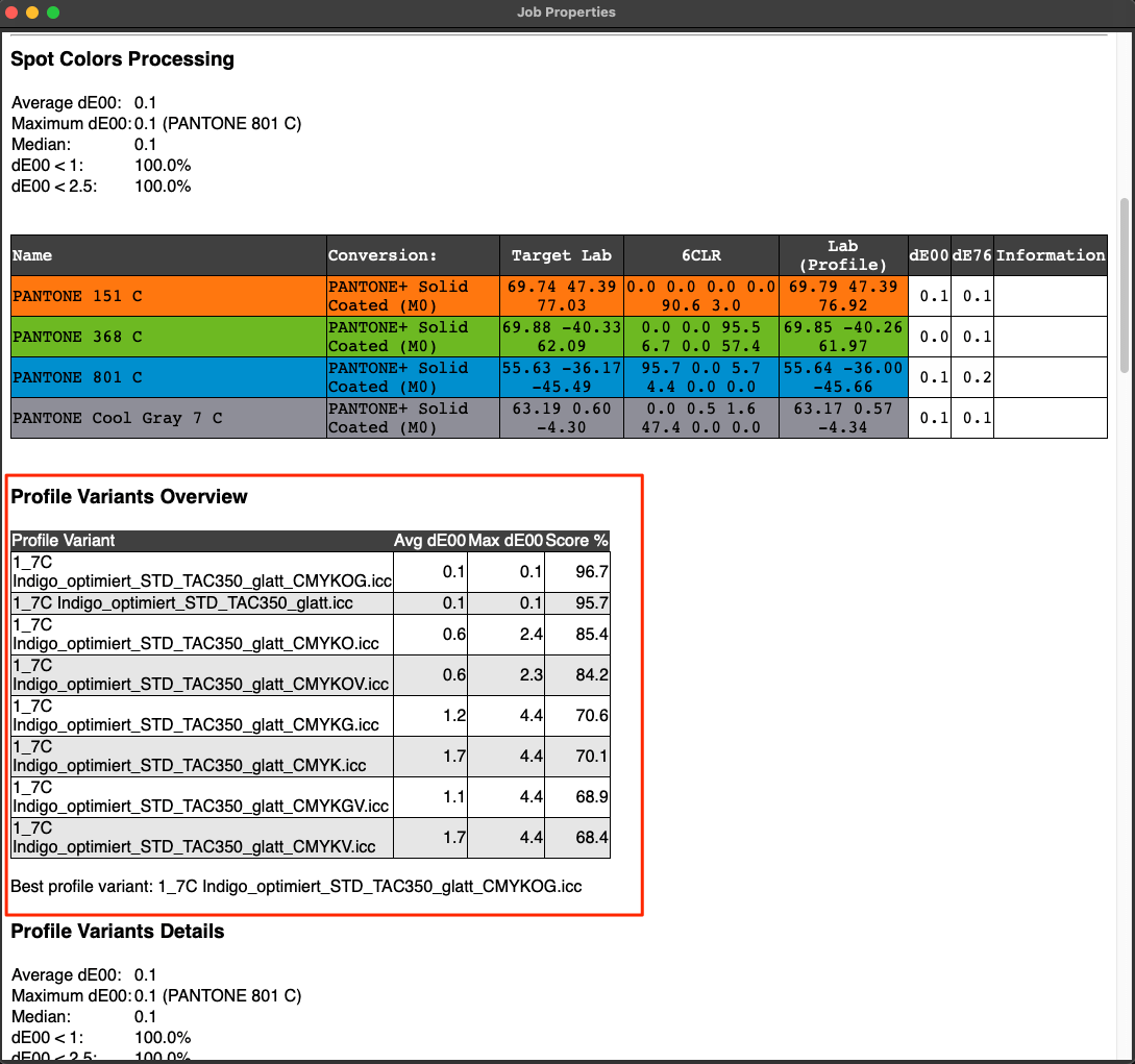
Note: For some use cases in digital printing saving channels means saving costs, and by using specific DeviceLink profiles, a reduction of channels is possible (e.g. removing Black from CMYK). Unused channels can be checked in the Job Report as those channels are marked either “-” or “0”.
If the Job Report is to be saved automatically or used for automation with other tools such as Enfocus Switch or Impressed IWS, the new Raw data in XML format should be used. The information can be found in “ConvertedDocumentProperties” in “InkInfo“.
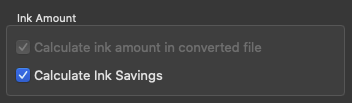
Calculate Ink Savings calculates the overall amount of CMYK ink saved when applying SaveInk profiles to each individual file. This calculation can be activated either manually with the Calculate Ink Savings checkbox or automatically when creating a SaveInk queue with the Auto Setup Wizard. The savings are indicated in percent in the Processed Jobs table of the Overview window and in the Job Properties window. The ink savings are displayed separately for each calculated file. To view the Job Properties, right click on a file in the main Overview/Processed Jobs window and select Show Job Properties.
Note: If Calculate Ink Savings is enabled, the checkbox Calculate ink amount in converted file is also enabled.
A SaveInk Report can be generated via the Tools menu. This report generates a detailed overview of each SaveInk queue that’s been set up and the jobs that were processed. The overview lists the overall ink savings across all queues, the savings per queue and the savings per job which can be beneficial when calculating costs. Reports can be created as PDF, TXT, HTML or XML files.
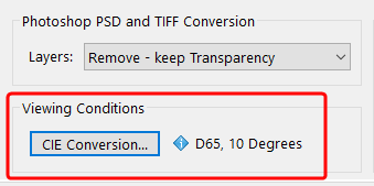
Photoshop PSD and TIFF Conversion
ZePrA 7 and higher allows to convert Photoshop PSD and TIFF files with layers. Layers can be deleted or retained depending on the requirements for further processing of the image files.
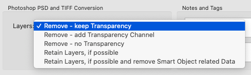
- Remove – keep Transparency
Considers only visible layers for conversion. All image elements and text are color converted. Removes layers but transparent areas can still be used and seen. With regard of layers the resulting image will be similar to Photoshop’s Merge visible option.
Note: Make sure to enable only those layers of the PSD file that are supposed to be visible in the converted file before converting with ZePrA. - Remove – no Transparency
Results in a converted PSD file without any layers and without transparency. With regard of layers the resulting image is similar to Photoshop’s Flatten option. - Remove – add Transparency Channel
Generates a converted file that has no visible transparency (the areas with checkerboard are gone). Visibly the file looks the same as converted with Remove – no Transparency. In contrast to this option all areas that had transparency in the original file are retained and added in an alpha channel called Transparency. This allows for further editing of the alpha channel mask in Photoshop. The mask can as well be used for reintroducing the transparency into the file, if required.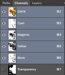
- Retain Layers, if possible
Retains all layers and their visibility status, if this is possible. All layers will be converted including those that are disabled. Colors in text and effects are converted as well.
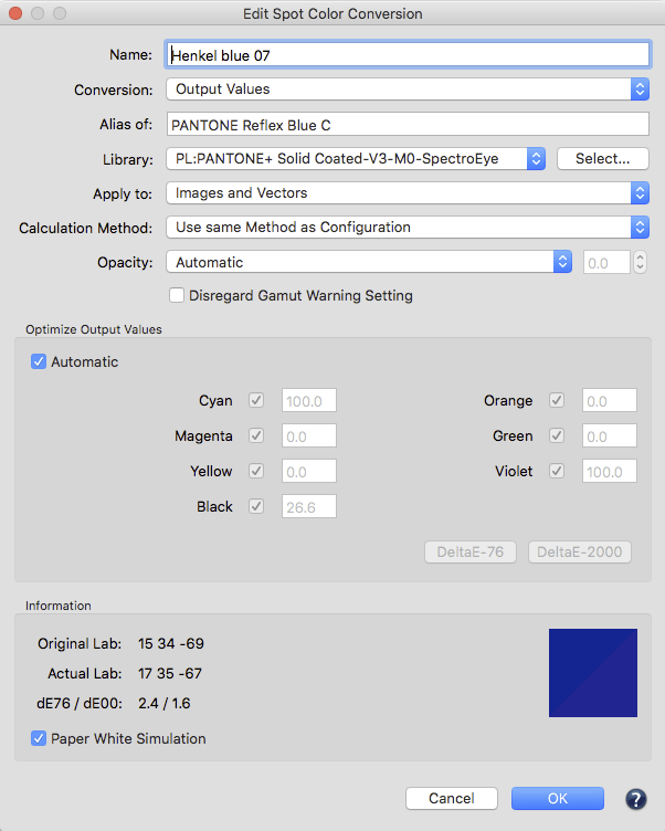
Spot color conversion to CMYK while retaining layers: Each spot color that is converted to CMYK is in a separate layer after conversion. This way, the spot color conversion can be adjusted separately. This is a special feature of ZePrA.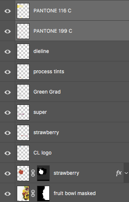
Please note that the color rendering of the spot colors converted in Photoshop depends on the general rendering of layers in Photoshop which may not be visually perfect. The big advantage of these additional layers is that it is still possible to edit the spot color conversion while retaining layers and transparent areas.
Notes: ZePrA allows conversion to a Multicolor profile but in this case layers can not be retained. The reason is a limitation of Photoshop which does not support spot colors in a layer – please read the General Considerations below. If ZePrA recognizes a Multicolor target profile layers will be removed and a job warning is displayed.
If ZePrA can’t convert a text layer, the following job warning is displayed: A text layer has possibly not been color converted. - Retain Layers, if possible and remove Smart Object related data
Retains all layers and their visibility status, if this is possible. All layers will be converted including disabled layers. Smart Objects are removed and a layer is added containing a correctly color converted image representation of the object.
Note: Smart Objects in Photoshop can be external files and as they cannot be color converted it may be risky to keep them in the converted file. Use this option to remove all Smart Object related data.
General Considerations
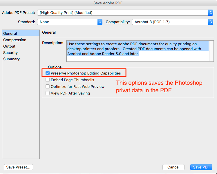
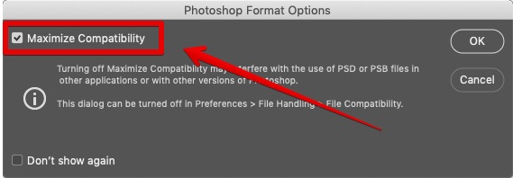
- Photoshop PSD files with layers created with current versions of Photoshop may not be compatible with other applications, such as ZePrA. To avoid such problems, activate the checkbox Maximize Compatibility for PSD files with layers in the Photoshop Format Options.
- Layers and transparency are special Photoshop functionalities which may not be used by other applications.
- Especially for TIFF files layers and transparency will mainly work in Adobe Photoshop and partly in other Adobe applications but might not work in other apps. In order to retain transparency in TIFF files, for example to place the file in Adobe InDesign, you should check the Save Transparency checkbox in Photoshop’s TIFF Options dialog. If this option is enabled placing works also with the converted TIFF file, with the exception that the preview in InDesign’s placement options dialog is opaque.
Note: TIFF is supported by ZePrA if the Pixel Order is set to Interleave. The alternative pixel order Per Channel is not supported. - Color conversion images with retaining layers may yield different visual results compared to the flattened images. This depends on several aspects which can all have a big impact on the color view of converted images with layers in Photoshop:
a) Photoshop always calculates the preview of an image with the layers in its stacking order and visibility. This is true except for spot colors which are overprinted on top of the fully composited image.
b) Spot colors can not be in a layer. Read more about the limitations of spot colors in Adobe Photoshop’s online help.
c) The layer effects used: Adjustment layers are not converted when converting with retaining layers in ZePrA which can have a different effect on the converted file than the adjustment layer had on the original file. In some cases adjustment layers can’t work properly in Photoshop if the color space has changed after conversion. A job warning message will be displayed if a color space change (called mode change in Photoshop) has been done with files with adjustment layers.
d) Photoshop layers with smart objects will not be converted when converting images with layers and layers are to be retained. In this case the content of the smart object will not be changed and left the way it is. This can cause some issues, especially if color spaces have been changed (e.g. RGB to CMYK).
e) Transparency effects added to layers might look different after conversion.
Note: If color accuracy is the most important aspect of your PSD and TIFF file conversion, we recommend using one of the layer removing options. If it is more important to edit layers after color conversion rather than color accuracy then use the Retain Layers option.
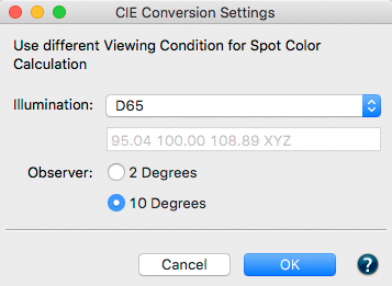
Viewing Conditions
The CIE Conversion converts data into another viewing condition, e.g., to change the illumination and observer angle for the textile industry, where D65 and a 10-degree observer are used as standard. The CIE Conversion is applied to spectral data only.
Notes:
- ZePrA automatically determines and applies the Viewing Condition included in CoPrA printer profiles.
- The Viewing Conditions information is listed in all report types if deviating from standard D50, 2 degrees (job reports, spot color reports, spot color iteration and DeviceLink iteration reports).
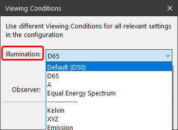
The Illumination drop-down menu contains the following options:
- D50, D65, illuminant A or the Equal Energy Spectrum. Typically, printer profiles are created for D50 viewing conditions.
- Manual input of Kelvin or XYZ values.
- Emission (Open File): Selection of spectral emission readings (as CxF or text file) of a specific light source. The data can be loaded or dragged and dropped onto the selection. ColorAnt can also extract data (the white point) from a measurement file and display these values.
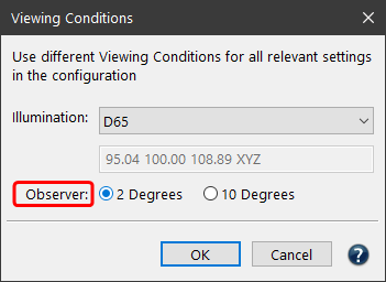
Observer: For spectral measurement data, the Observer can be changed from 2 Degrees to 10 Degrees.
Exceptions
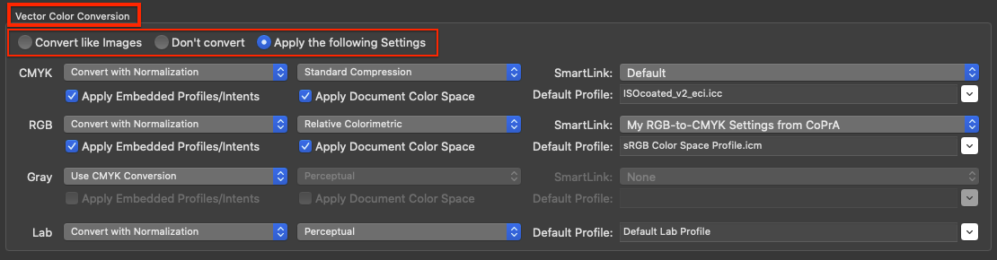
Text and vector graphics are independent objects in PDF documents. For both types of objects, it can be prevented that purely black vector graphics or texts are built up in four colors after an ICC conversion.
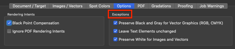
Preserve Black and Gray for Vector Graphics (RGB, CMYK): Converts RGB black to pure CMYK black and preserves pure CMYK black. All gradations of gray created as vectors are also preserved. A 50% K gradation remains unchanged at 50% K. A medium gray RGB gradation with RGB=128/128/128 turns 50% K after conversion from RGB to CMYK.
Leave Text Elements unchanged: Converts only vector graphics, but not text.
Note: Both functions are not necessary when using ColorLogic DeviceLink profiles when the exceptions for 100% Black and Gray have been selected, since these DeviceLink profiles maintain 100% Black and Gray, while Gray is also adjusted in brightness and linearity. We therefore recommend using such DeviceLink profiles.
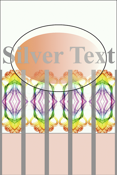
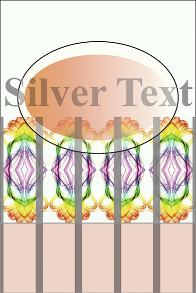
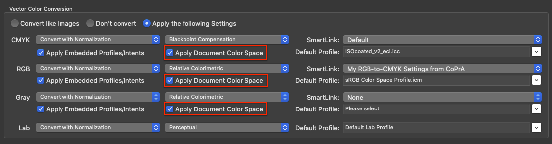
Preserve White for Images and Vectors: When enabled, areas with 0% ink are preserved and will not be color managed.
Typically, when converting files, image and vector areas that were originally designed to be transparent and do not use ink (e.g., 0% ink or white) are also converted using the selected color management settings. When using perceptual rendering intents this leads to 0% ink in the converted file, and in case of proofing with the absolute colorimetric rendering intent this results in a paper simulation. In both cases, ZePrA ensures that the correct paper white (either 0% ink or paper simulation) is used and will place the paper white under the entire art box. In some cases, especially when printing on transparent foils and using white inks, this is undesirable since areas with 0% ink are supposed to be transparent after conversion.
Note: When the exception is enabled and there is a strong paper simulation in the converted file, there will be a hard edge between the preserved white and close colors such as 1%.
Sharpening (ZePrA 12 and lower)
Lack of sharpness is usually already compensated for by the camera or the integrated recording software. In addition, the Sharpen function is also used as a creative option in image processing programs.
ZePrA uses the “Unsharp Masking” algorithm for sharpening, which is also used by Adobe Photoshop. Sharpening images involves intensifying differences in brightness or color between two adjacent pixels. This can lead to lines between image areas with different brightness/color when sharpening strongly.
With ZePrA’s Sharpen function, images can be sharpened after color conversion. In media production, there are several reasons for using sharpening:
- To compensate for digitalization shortcomings (digital photo or scan)
- Sharpen as a creative option
- To compensate for loss of detail after changing the image resolution
- To compensate for shortcomings in the printing process (e.g. screening)
Sharpening of image data can be applied to individual color formats (CMYK, RGB, Multicolor, Gray, Lab) or all color formats simultaneously.
Sharpening generally takes place after color conversion. In certain situations, for example when a transparency reduction is to be performed at the same time, images are sharpened before conversion.
Sharpening Presets
Three presets are available for sharpening – in addition to the option not to sharpen. Custom settings are also possible.
Note: Files that were created in a controlled, in-house working environment can usually be sharpened stronger.
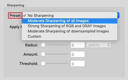
Preset
Moderate Sharpening of all Images: Recommended presetting. Compensates for typical anomalies in the printing process.
Strong Sharpening of RGB and Gray Images: For media-neutral workflows that frequently use high-resolution RGB and Gray images.
Moderate Sharpening of downsampled Images: Compensates for minor sharpening losses that can occur, for example, when downscaling.
Custom: Allows all sharpening parameters to be defined individually. An Amount of 80% and a Threshold of 8 usually provide stable results.
The following parameters can be set individually:
Radius: The wider the radius, the wider the line created during sharpening. The choice of the correct radius depends on several factors, such as the usual viewing distance or the resolution of the printing process used. For more information see the section on the relationship between scaling and image resolution below.
Amount: Indicates the intensity of sharpening in relation to the selected radius and should take into account the sharpness of the original image and the anomalies of the printing process.
Threshold: Describes the difference in color or brightness at which the sharpness filter will apply. The lower the threshold, the more image areas will be sharpened and the greater the risk that unwanted image artifacts will also be sharpened. The usual values here are 2 to 10.
Tip: Too much sharpening due to an excessively high Radius and too much Amount can lead to an unnatural image display. Depending on the Sharpening settings, artifacts that were previously not visible can now be visible and over-emphasized. This applies in particular to the square patterns of JPEG compression or the image noise in dark areas of digital photos.
To learn more about the special work processes/flattened transparencies and sharpening, see Working with Transparencies.
Image-based vs Output-based Sharpening Radius
The sharpening Radius can be defined in two different ways: image-based or output-based.
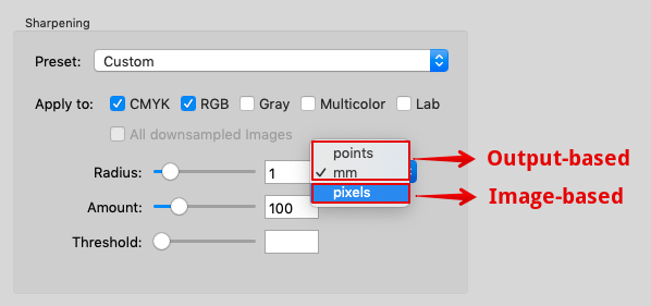
Image-based sharpening: The Radius is specified in pixels. With a radius of 2 pixels, the effective width of the sharpening is correspondingly 2 pixels. Corresponds to the method of the “Unsharp Mask” filter in Photoshop.
If a sharpened image is placed in a layout program, the visually perceived effective width or radius of the sharpening depends on the image resolution in pixels per inch (ppi) and the scaling in the layout program.
Example: If you specify a radius of 2 pixels for an image with 288 ppi resolution and place it in a layout program with a 100% scale, the visually perceived radius of sharpening is 0.5 points (0.18 mm). This results from the fact that 72 points represent one inch. For an image with 288 pixels per inch, one pixel is 0.25 points (0.09 mm) wide.
Output-based sharpening: The sharpening radius (in points or mm) remains the same for images with different resolutions or scaling in the layout program. Since output-based sharpening mainly compensates for detail losses of the output system (e.g. due to rasterization), it is ensured that the sharpening radius of all images in the document counteracts the detail loss of the output in a comparable way.
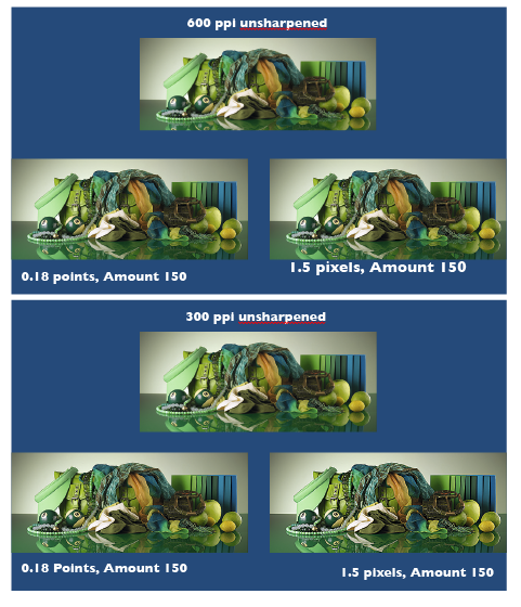
Correlations Between Scaling and Image Resolution
If you reduce the image from the previous example with 288 ppi resolution to 50% in the layout program, the image resolution changes to 576 ppi. An output-based sharpening with 0.5 points results in a doubled radius of 4 pixels.
Typical image-based sharpening radii of 300 dpi images with 100% scaling in the layout program correspond to the following values of output-based sharpening in points:
0.8 pixels = 0.19 points
0.9 pixels = 0.22 points
1.0 pixels = 0.24 points
1.1 pixels = 0.26 points
1.2 pixels = 0.29 points
1.3 pixels = 0.31 points
1.4 pixels = 0.34 points
1.5 pixels = 0.36 points
1.6 pixels = 0.38 points
Converting the Width of an Image Pixel of Any Resolution into Points
The following correlation applies:
Radius (in points) = 72 / Image resolution (in ppi)
Note: Adobe Photoshop uses the term dpi (dots per inch) instead of ppi (pixel per inch).
The radius of the sharpness should not be larger than the raster width in the print. The following table shows the raster width and the radius of the sharpness (in mm) in a ratio of 1:1:
60 l/cm= 0.17 mm (0.48 points)
70 l/cm = 0.14 mm (0.40 points)
80 l/cm = 0.13 mm (0.37 points)
90 l/cm = 0.11 mm (0.31 points)
100 l/cm = 0.10 mm (0.28 points)
110 l/cm = 0.09 mm (0.26 points)
120 l/cm = 0.08 mm (0.23 points)
200 l/cm = 0.05 mm (0.14 points)
l/cm = lines per centimetre
If you are printing with a 70 l/cm screen ruling, the radius should be 0.14 mm or less.
The sharpening radius (in mm) corresponding to a given screen ruling can be calculated using the following formula:
Radius (in mm) = 10 / screen ruling (in lines per centimeter)
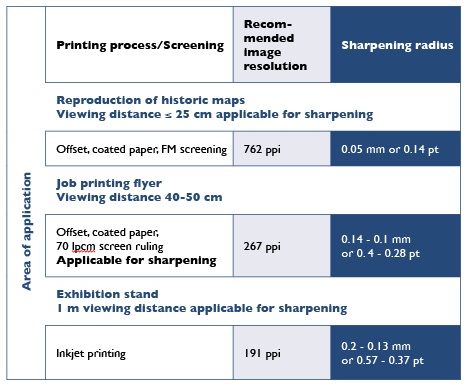
Sharpening and Image Resolution in Relation to Viewing Distance, Printing Process and Screen Ruling
The radius of the sharpening can be determined by taking the viewing distance, the printing process and the screen ruling into account.
The maximum resolution of the eye – depending on the contrast of the structures and the position in the field of view – is approximately 0.2 mm (127 pixels per inch) at a viewing distance of 1 m or approximately 0.05 mm (508 pixels per inch) at a viewing distance of 25 cm.
The image resolution and effective width (or radius of sharpening) should only be adjusted to the print resolution if the selected printing method is capable of reproducing details in the resolution of the eye for the respective viewing distance. To be on the safe side, the image resolution should be approximately 1.5 times higher than the print resolution or the assumed viewing distance.
Example 1: An offset print with a screen ruling of 70 l/cm (178 lpi) can reliably reproduce details up to 0.14 mm wide, which also defines the maximum radius of sharpening. With a 1.5-fold reserve, the image resolution should be at least 267 ppi.
Example 2: At a trade fair stand viewed from a distance of 1 m, the normal eye can detect details down to approximately 0.2 mm, which determines the radius of sharpening. With a 1.5-fold reserve, an image resolution of 191 ppi is sufficient.
Notes and Tags
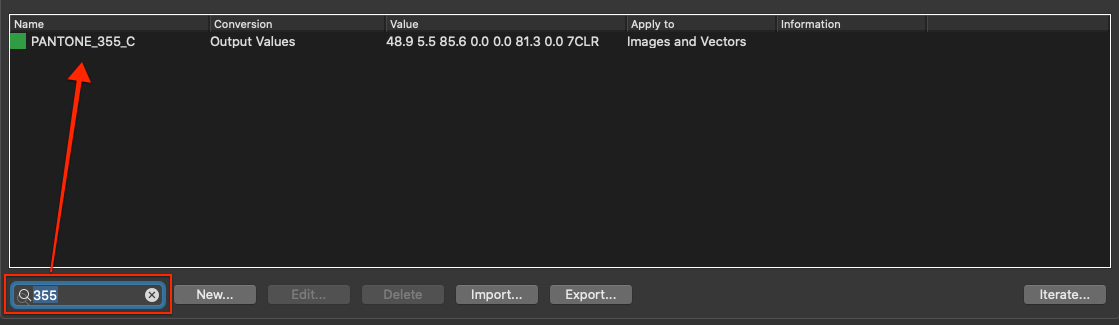
Custom notes and tags are linked to the selected configuration. They can then be used to find the associated configuration using the Search.
In the Overview dialog, for example, a tag (or note) can be used to find configurations based on that tag (or note).
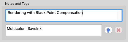
Tags can be added using the Add button and can be removed from a configuration using the Delete button. Clicking on the Add button allows either selecting an existing tag or creating a new tag.
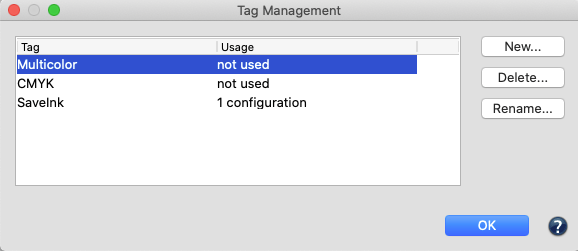
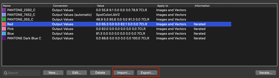
Tag Management
All existing tags are listed in a table under Tag Management. It can be opened via the Tools menu and is especially useful if tags are to be edited or removed from several configurations. The Usage column indicates how many configurations use a certain tag. With the buttons on the right New tags can be entered and existing tags can be removed (affects all configurations) or renamed (also affects all configurations).