
Using Profile Manager
Profile Manager allows viewing, organizing, analyzing, comparing or even adapting profiles without leaving the CoPrA environment. The main window shows all profiles stored on the system. The unique ability of Profile Manager to display and handle all types of profiles, including DeviceLink and Multicolor profiles, makes it the ultimate tool for everyday color management.
Profile Manager includes six different tabs (General, Curves, Gamut, Colorants, Workflow, Notes) which provide access to all important functions. Apart from that, it allows to quickly and comprehensively verify the quality of profiles by means of a Profile Report.
Profile Manager Features
Main window features
Profile Filter
Profile Filter: Offers various filters for searching profiles and a profile list showing all available profiles on your system.
Profile Filter
Filters for Searching Profiles
Using the four drop-down menus and the text input box narrows down the search to find profiles more quickly.
Device Class: Displays all profiles of a specific device class. You can exclusively display Input (scnr), Output (prtr), Monitor (mntr), DeviceLink (link), Color Space (spac), Abstract (abst) or Named (nmcl) profiles.
Choosing a Device Class
DCS and PCS: With DCS (Device Color Space) and PCS (Profile Connection Space) all profiles of a specific color space can be viewed.
Select a color space
Profile Type: Limits the search to profile types. Returns fast search results, especially in combination with Search for file name.
Choosing a Profile Type
Search for: Enter a search term to search specifically for a particular text in the profile name. For example, by entering 'preview' all preview profiles are shown. Searching for Name, Manufacturer, Creator, Date, Notes, System Profiles, SaveInk Profiles, Updated Profiles or Correction DeviceLinks is also possible.
Note: Narrowing down the search to a specific date can be useful to display all profiles that have been created on a given day.
Invert: All filters and keywords can be inverted by clicking on the corresponding checkbox. For example, by selecting DeviceLink under Device Class, all DeviceLink profiles will be shown. By activating the checkbox Invert, all profiles except DeviceLink profiles will be shown.
A click on X resets all filters and displays all profiles.
Profile List
The list of available profiles is updated automatically every time Profile Manager is accessed (at program start or whenever it is brought to the foreground).
All columns of the list can be sorted by clicking on the column title.
The Date column displays the creation date of the respective profile.
Context menu
A right-click on a profile opens a context menu. The following options are available (depending on the profile type and the licensed modules):
Right-click contextual menu options
The entries Create Profile Report (PDF)/(XML), Save Preview Profile, Calculate Gray Profile and Smooth Profile LUTs are only available if a valid license for the corresponding modules exists.
The context menu also allows you to create ACV or XML curves from a selected Linearization DeviceLink profile.
Extract source and target ICC printer profiles of DeviceLinks
Embedded source and target ICC printer profiles of DeviceLinks can be extracted using the Install embedded profiles option (only available when embedded profiles are present). This is useful if you have been sent a DeviceLink profile and the required printer profiles are not available on your system.
Open the context menu by right-clicking on the respective DeviceLink profile and click on Install embedded profiles. The extracted profiles are stored in your profile library. A message at the bottom of the window confirms the action and the location.
Extracting DeviceLink profiles
Create Profile Report (PDF/XML): Based on the selection of the profiles the profile reports will be created and stored in the dedicated Documents folder. Multiple reports can be created simultaneously.
macOS: /Users/USERNAME/Documents/CoPrA/Reports/
Windows: C:\Users\USERNAME\Documents\CoPrA\Reports
Create Multicolor Profile Variants: This option creates various profile combinations of the selected Multicolor profile. All possible profile variants such as 3CLR, 4CLR or CMYK+ can be created automatically at the same time, but they can be created individually as well.
Multicolor profile variants, e.g., of a 7C output profile, are useful for determining whether fewer than 7 colors, e.g., 5 or 6 colors, or even the CMYK colors alone are sufficient for printing a given job. After all, it is not always necessary to use all available process colors and costs can be saved by using fewer channels.
Note: The creation of 4CLR variants also creates a CMYK profile. For CMYK+ profiles, 5CLR and higher variants are created using CMYK and all spot color combinations.

The four buttons below the profile list differ for macOS and Windows (see screenshots).
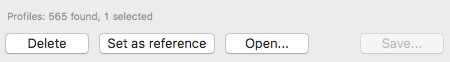
macOS buttons
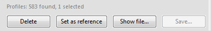
Windows buttons
Delete: Deletes the selected profile.
Set as reference: The selected profile acts used as reference profile for a gamut comparison with another profile. It is displayed at the right bottom of the window under Reference profile and can be activated or deactivated by its checkbox. After activation it is available for a Gamut Comparison (see below) and will be shown in the 3D and 2D view of the gamut together with the selected profile. To view only the selected profile, hide the reference profile by unticking the checkbox.
Save: Saves any changes to a given profile.
macOS:
Open: Opens the ICC profile using the default system program. macOS opens the ColorSync Utility which displays individual tags and tables of the selected profile.
Windows:
Show file: Opens the folder in which the selected profile is stored.
General
Description: Displays the name of the profile which can be changed and saved by clicking on Save.
Copyright: Displays the non-editable copyright of the profile.
Header: Shows all important entries in the profile header.
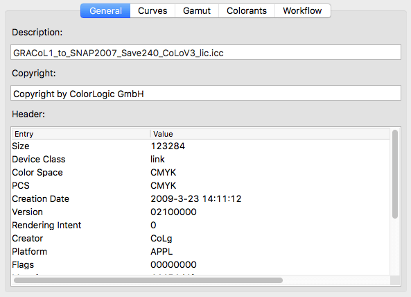
General profile information
Gamut Comparison
A Gamut Comparison can be created by clicking on the double arrow icon at the bottom right of the window (see screenshots). In this process the gamut size of the selected profile is calculated and compared to the gamut size of the selected Reference profile (see above). The selected profile is displayed under Profile path.
The gamut Lab Volumes can be calculated without a Reference profile allowing for a quick check of the gamut size for selected profiles (Sample).
Comparing Gamuts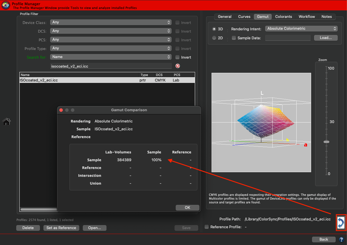
Curves
Shows the curves for the selected profile. For each Device Class only the appropriate options are available in the drop-down menu, e.g. for DeviceLinks, device profiles or monitor profiles (see screenshots).
Drop-down menu for DeviceLink profiles
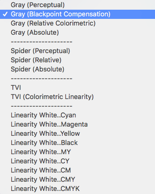
Drop-down menu for device profiles
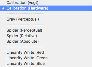
Drop-down menu for monitor profiles
For example, the purity of the channels can be displayed for DeviceLinks. For printer profiles you can view the curves for the gray balance, but many more curves and color space views are available additionally. Specific curves are available in the drop-down menu for monitor profiles. Try out the various options and curves to get an overview of the characteristics of your profiles.
A special feature of Profile Manager is the possibility to view the gray balance of a printer profile for different rendering intents in the profile. Thus the gray balance can be viewed using the relative colorimetric rendering intent with black point compensation (see screenshot).
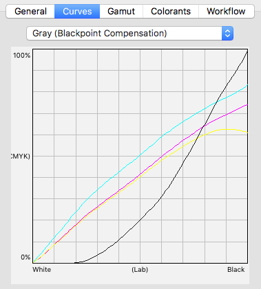
Viewing gray balance
Gray balance of a CMYK printer profile when using the relative colorimetric rendering intents with black point compensation.
Gamut
The tab Gamut displays either a 2D or a 3D representation of the color space for the selected profile (see screenshots).
For CMYK printer profiles, the maximum gamut is displayed (disregarding separation limitations). The gamut display for Multicolor printer profiles is limited.
The gamut of DeviceLink profiles is displayed regardless of the color spaces of the source and target profiles (e.g., RGB-2-RGB, CMYK-2-xCLR, RGB-2-xCLR) but can only be displayed if the source and target profiles are found on the system.
The preview reflects all DeviceLink settings (Rendering Intent settings, Exceptions settings, …) in 2D and in 3D.
By selecting comparison profiles, the gamuts of two profiles can be compared in the 3D view and up to three profiles in the 2D view.
2D gamut view
Lightness: The Lightness is used to view the gamut border of a lightness slice of the selected profile. It can be adjusted with the mouse wheel or by entering the value directly in the input field.

ab-Projection: Tick this checkbox to show the entire gamut as a flat projection on the ab plane.

3D gamut view

The 3D view features a rotatable gamut
Gamut Zoom: Change the zoom factor with the mouse wheel, a shortcut (macOS: CMD+ / CMD-, Windows: STRG+ / STR-) or by entering the value directly in the input field.
Note: The default 3D gamut viewing method of CoPrA 9 and higher is based on a 1:1:1 axis ratio. This means that the axis ratio of L to a+ (a-) as well as to b+ (b-) is identical. Up to CoPrA 8, the L axis was twice as long in ratio (see screenshots).
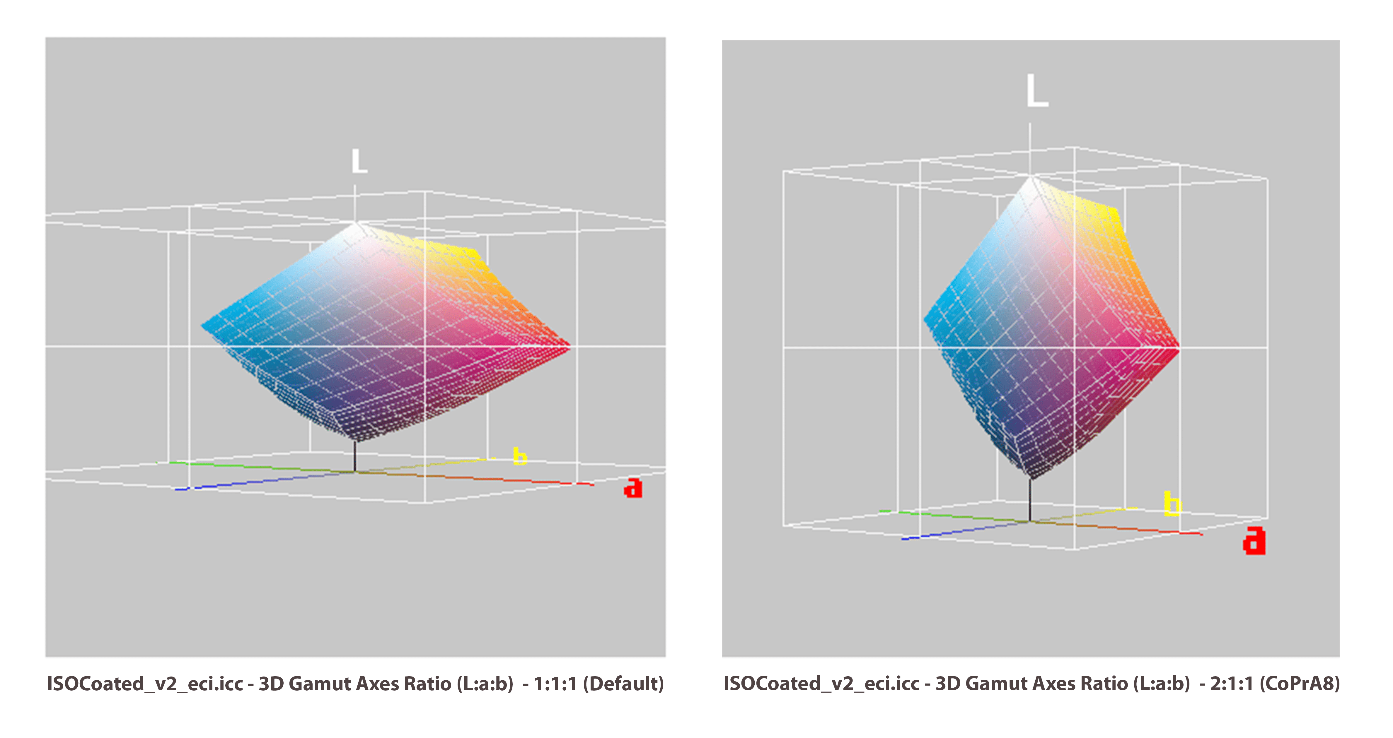
To use the 2:1:1 axis ratio view used in CoPrA 8 or older, change the 3D Gamut Axes Ratio (L:a:b) setting under Profile Manager options in the Preferences.

Please note that the 3D gamut view options also affect the gamut view in the Printer Profiling tool on the Color Generation tab.
Context menu of the Gamut view
A context menu that provides additional viewing options can be opened by right-clicking on the gamut view. The Grid, Axes and Axes Labels can be switched on and off here. When analyzing Sample Data, the sphere size can also be increased or decreased using a key combination (macOS: Option+ / Option-, Windows: ALT+ / ALT-). For a better display of the Sample Data, the gamut view can be switched between a Gamut Surface view and a polygonal gamut grid view.
The options last used in the Gamut view are saved and applied again when CoPrA is restarted.

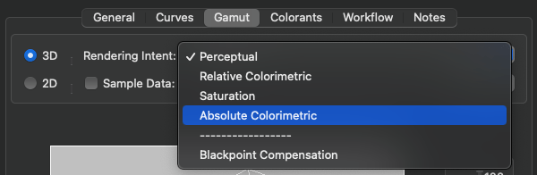
Rendering intent
The displayed gamut changes according to the selected Rendering intent.
Sample Data
Sample data can either be image files (TIFF, JPEG or PSD files) or measurement data as text files (CGATS files in text or XML format, CxF files or ACO files) or a single Lab value entered manually. Based on the position of the values in the Lab color space the 3D or 2D representation quickly reveals whether images or color values can be reproduced within the desired printer gamut using the set Rendering intent. Select 3D and move the mouse pointer over the color patches to highlight them and to display their name, Lab value and their deltaE (in dE76) to the gamut border of the profile.
Note: The deltaE is only appropriate for the Absolute Colorimetric Rendering Intent and will not be shown for other rendering intents.

Comparing sample data to the gamut
Note: Image files (JPEG, TIFF or PSD) will be split into color patches using a lower resolution and will then be converted directly to Lab using either the embedded profile or the default profile and the set Rendering intent. The image will be converted and displayed as dots. The selected profile is shown in brackets behind the file name. If no profile is embedded AdobeRGB is used for RGB images. CMYK images without a profile are assumed to be in the CMYK color space of the selected profile. The used color space is always shown in brackets behind the file name.
Comparing profile gamuts
Comparing profile gamuts in 2D view
Profile Selection: The gamut of the Selected Profile can be compared to the gamut of up to two Comparison Profiles selected in the Profile Selection. These comparison profiles can either be set via the context menu of the profile list or via the Load option of the context menu that can be accessed by right-clicking the area next to Comparison Profile 1 and 2.


The color of the outlines of the individual profiles can be changed by clicking the color field and using the tools provided.

Comparing gamuts in 3D view
Profile Selection: The comparison profile can either be set via the context menu of the profile list or via the Load option of the context menu of Comparison Profile 1 (accessible by right-clicking in the area next to Comparison Profile 1).

Since only two profiles can be compared in the 3D gamut view, Comparison Profile 2 is grayed out here.
In the 3D view, Comparison Profile 1 is displayed in a semi-transparent white color.
Colorants
The Colorants tab shows the Colorant Table of the profile (if available, for example, for Multicolor profiles and Multicolor DeviceLinks). Both the Name and the Lab Values can be edited and saved. A small color patch at the end of each line shows the current Lab value in true colors. In addition, creating a colorant table or loading an existing table is possible.
Note: If Multicolor profiles do not list these tables correctly, it is an error in these profiles which can be corrected by using the function Create Table.
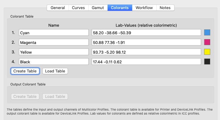
Creating tables for a profile
Note: Printer profiles only have one colorant table, DeviceLinks, however, may have up to two colorant tables (for Multicolor-to-Multicolor-DeviceLinks).
Workflow
In the tab Workflow the Source and Target Profile of a DeviceLink and the PDF/X Information can automatically be entered in the profile which allows the automatic creation of configurations in ColorLogic’s color server ZePrA. This requires the source and the target profile of the DeviceLink. ZePrA then automatically reads out the information about source and target profiles as well as the PDF/X information from the loaded DeviceLink and applies them in the configuration (PDF/X information can be entered for CMYK and Multicolor printer profiles or DeviceLinks).
The tab Workflow allows the user to add this information to self-created profiles. Profiles of other manufacturers can also be optimized for ZePrA's workflow.
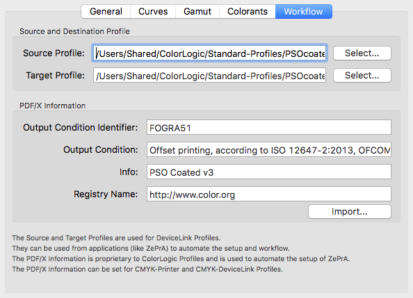
Adding PDF/X information
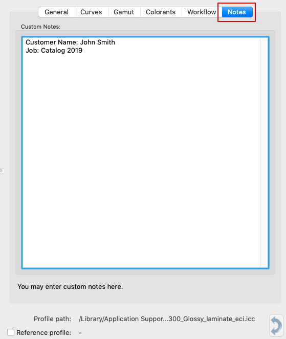
Notes
The Notes tab allows to leave custom notes linked to the selected profile. These notes can easily be found later using the Search for function under Profile Filter. Simply select Notes in the drop-down menu and enter the search text in the box below.
Example: Leave the name of a customer as a note in the profiles you have created for that customer. If you search for these profiles later, simply enter the customer's name in the Search for function set to Notes and all profiles with its name will be listed.